The simple configuration of a transformerless power supply circuit presented below is able to provide high current at any assigned fixed voltage level. The idea seems to have solved the problem of deriving high current from capacitive power supplies which earlier seemed a difficult proposition.
Introduction
I have discussed a few transformerless power supply circuits in this blog which are good only with low power applications, and tend to become less effective or useless with high current loads.
The above concept utilizes high voltage PP capacitors for dropping the mains voltage to the required level, however it is unable to raise current levels as per any desired particular application.
Although, since the current is directly proportional to the reactance of the capacitors, means the current can be lifted just by incorporating more capacitors in parallel.
But this puts a risk of high initial surge currents which might destroy the involved electronic circuit instantly.
Adding Capacitors to Increase Current
Therefore adding capacitors might help to increase the current specs of such power supplies but the surge factor must be first taken care of for making the circuit feasible for practical usage.
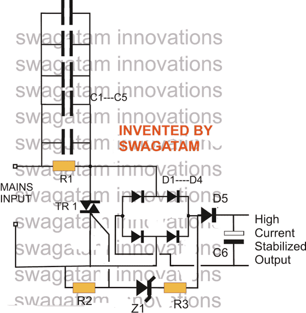
The circuit of a high current transformerless power supply explained here hopefully, effectively handles the surge developing from power transients such that the output becomes free from the dangers, and provides the required current supply at the rated voltage levels.
Everything in the circuit is kept just as its old counterpart, barring the inclusion of the triac and zener network which actually is a crowbar network, used for grounding anything that goes above the rated voltage.
In this circuit the output would hopefully provide a stable voltage of around 12+ volts at around 500 mA of current without the dangers of any accidental voltage or current influx.
CAUTION: THE CIRCUIT IS NOT ISOLATED FROM MAINS AND THEREFORE INVOLVES HIGH RISK OF ELECTROCUTION, APPROPRIATE PRECAUTION NEEDS TO BE EXERCISED.
UPDATE: A better and a more advanced design can be learned in this zero crossing controlled surge free transformerless power supply circuit
Parts List
- R1 = 1M, 1/4W
- R2,R3 = 1K, 1/4 WATT
- C1----C5 = 2uF/400V PPC, EACH
- C6 = 100uF/25V
- All DIODES = 1N4007
- Z1 = 15V, 1 watt
- TRIAC = BT136
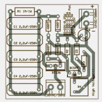
A neatly drawn PCB for the above high current transformerless power supply may be seen below, it was designed by Mr. Patrick Bruyn, one of the avid followers of this blog.
Update
A deeper analysis of the circuit showed that the triac was dumping a significant amount of current while restricting the surge and controlling the current.
The approach taken in the above circuit for controlling voltage and the surge is negative in terms of efficiency.
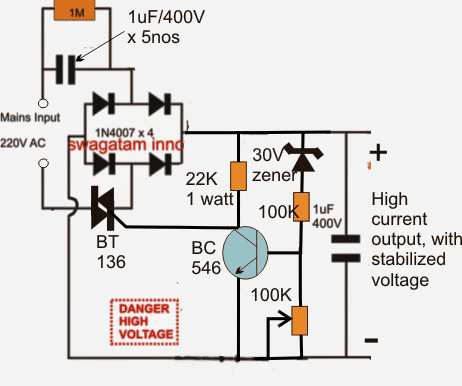
In order to obtain the intended results as proposed in the above design and without shunting precious amps, a circuit with exactly opposite response needs to be implemented, as shown above
Interestingly, here the triac is not configured to dump power rather it's wired in a such a way that it switches OFF power as soon as the output reaches the specified safe voltage limit, which is detected by the BJT stage.
New Update:
In the above modified design the triac may not conduct properly due to its rather awkward positioning.
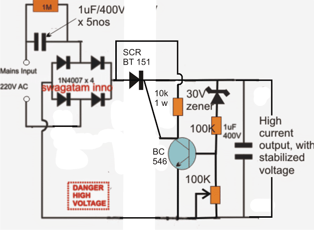
The following diagram suggests a correctly configured version of the above, which can be expected to operate as per the expectations.
In this design we have incorporated an SCR instead of a triac since the positioning of the device is after the bridge rectifier and therefore the input is in the form of a DC ripples and not AC.
Improving the above design:
In the above SCR based transformerless power supply circuit, the output is surge protected through the SCR, but the BC546 is not protected.
In order to ensure a complete protection for the entire circuit along with the BC546 driver stage, a separate low power triggering stage needs to be added to the B546 stage. The amended design can be seen below:
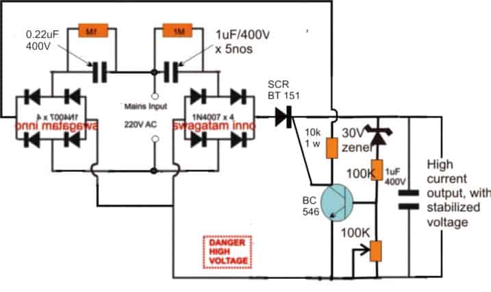
The above design can be further improved by modifying the position of the SCR as shown below:
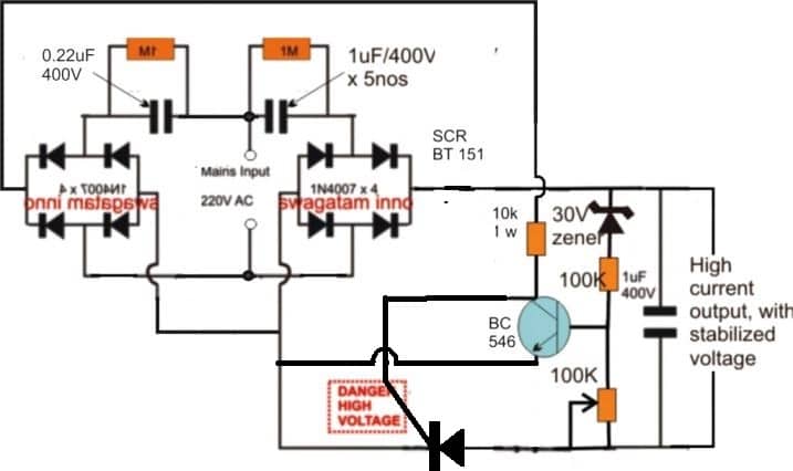
So far we studied a few transformerless power supply designs with high current specs, and also have learned regarding their different modes of configurations.
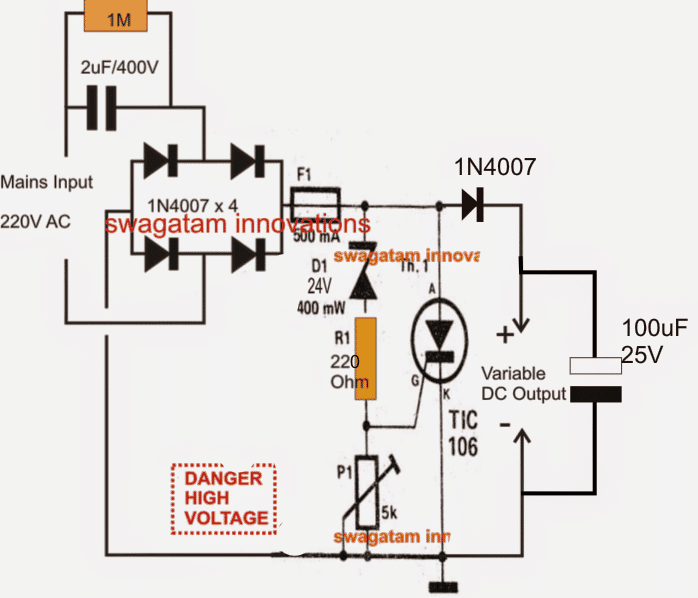
Below we would go a little farther and learn how to make a variable version circuit using an SCR. The explained design not only provides the option of getting a continuously variable output but is also surge protected, and therefore become much reliable with its intended functions.
The circuit can be understood from the following description:
Circuit Operation
The left side section of the circuit is quite familiar to us, the input capacitor along with the four diodes and the filter capacitor forms the parts of a common, unreliable fixed voltage transformerless power supply circuit.
The output from this section will be unstable, prone to surge currents, and relatively dangerous to operate sensitive electronic circuits.
The portion of the circuit on the right side of the fuse transforms it into a completely new, sophisticated design.
The Crowbar Network
It's in fact a crowbar network, introduced for some interesting functions.
The zener diode along with R1 and P1 forms a kind of voltage clamp which decides at what voltage level the SCR should fire.
P1 effectively varies the zener voltage from zero to its maximum rating, so here it an be assumed to be zero to 24V.
Depending upon this adjustment, the firing voltage of the SCR gets set.
Supposing P1 sets a 12V range for the SCR gate, as soon as mains power is switched ON, the rectified DC voltage starts developing across D1 and P1.
The moment it reaches the 12V mark, the SCR gets sufficient triggering voltage and instantly conducts, short circuiting the output terminals.
The short circuiting of the output tends to drop the voltage toward zero, however the moment the voltage drop goes below the set 12V mark, the SCR is inhibited from the required gate voltage and it reverts to it non conducting state.... the situation yet again allows the voltage to rise, and the SCR repeats the process making sure the voltage never goes above the set threshold.
The inclusion of the crowbar design also ensures a surge free output since the SCR never allows any surge to pass through to the output under all circumstances, and also allows relatively higher current operations.
Circuit Diagram
Another SCR based Circuit
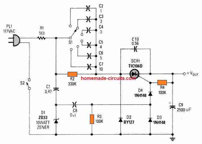
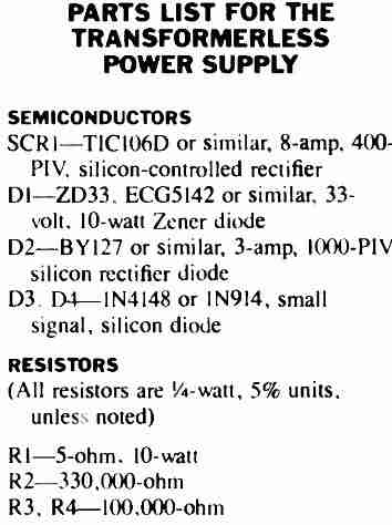
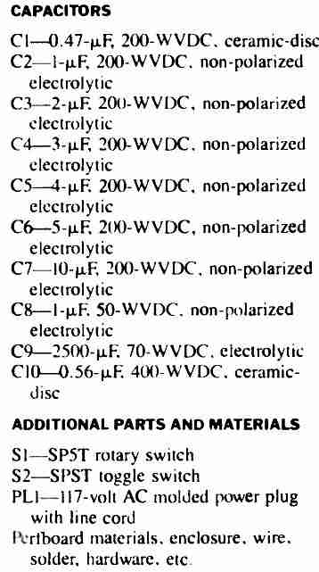
This SCR based high current Transformerless Power Supply consists of rather a few, easily accessible electronic parts.
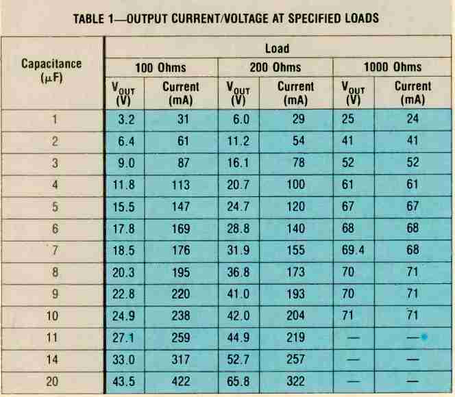
The output voltage level (and also the level of feasible current as provided in the Table I) is adjustable by rotating the rotary switch S1.
Table#1
Zero Crossing Controlled High Current Transformerless Power Supply Circuit
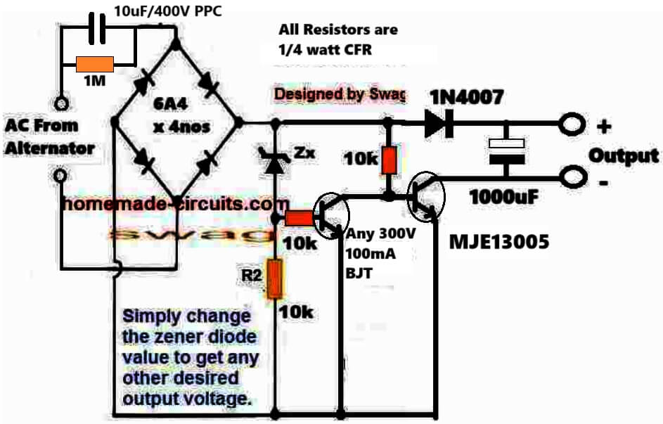
The following circuit shows how a zero crossing concept can be implemented to create an effective transformerless high current power supply circuit, which is highly customizable.
Advantages of this Circuit are as follows:
100% surge free ensures that the load, zener diode and the capacitor are completely safe all the time regardless of the input switching conditions of the power supply.
No heat dissipation ensures that the circuit's efficiency is maximum.
How the Circuit Works
We know that the main issue with transformerless power supply circuit is the switch ON surge current, which happens due to the sudden peak AC entering the electronic circuit connected with the power supply.
This sudden in-rush voltage and current leads to the burning of the vulnerable electronic components attached with the power supply.
This means that, if the load is allowed to be switched ON whenever the AC waveform nears the zero crossing then such mishaps can be avoided.
The above circuit does exactly this.
The NPN TIP122 conducts only when the AC waveform is below the zener value.
When the TIP122 conducts the AC waveform is already within the safe range of the load and this safe voltage gets stored in the 1000uF capacitor for powering the load.
The process continues for each cycle and only when the AC peak has dropped down safely to the zener value, which keeps the load powered consistently, with an optimized voltage and current inputs.


Questions & Answers
Thanks friend!
It feels very satisfying when I see readers succeed with my projects!
Yes, I'll be careful about somebody stealing my credentials, I appreciate your suggestion very much!
Many thanks!
Inteersting Info CM! I am sure the visitors would greatly benefit from this.
Actually I am already committed to sharing my exclusive ideas with the readers, if you think you have a better plans for me where you could use my innovations for generating some sort of income for both of us, then who knows I may slowly wind up here and start concentrating on the new job;)
Anyway, thanks a lot for showing your kind concerns! appreciate it.
Yes it may be tried for further reinforcement, with LM317 in its current regulation mode as discussed here:
https://www.homemade-circuits.com/2013/06/universal-high-watt-led-current-limiter.html
hello Swagatam,
can i use this circuit to run a 12V 0.2A dc cooling fan continuously ? if not why? what changes done with circuit, or what V/A rated fan i must use?
hello max,
yes i think you can give it a try. start with a 2uF/400v cap iniially for C1
Sir,
Are you test it…..
Because R2 is getting very hot…….
I am used in R2 1k 1 Watt……
PLZ solve my problem if you have any solution.,……
please don't become restless….the site is all about learning through discussions, experimentation, calculation etc.
Try using a higher value for R2, try a 10k, 1 watt resistor.
After running the 20W LED with 10uF for more than a month, it fuses suddenly. First LED fused, then C6 bursts (33uF/63V).
The reason I am suspecting:
I was driving another 12V/0.056A fan for cooling from same 36V O/P with resistance driver.
1. First resistance (1W) driver fails, which fails the fan to run.
2. LED get hot and burnt.
3. Peak voltage increased across C6 and it burnt.
Another possibility of damage: The power extraction may be too high and those Chinese LED will be certified someday for its voltage and current 🙂
Next modification I am thinking:
1. to use 30W LED to get 20W power. You will get 30% margin of protection.
2. Stable circuit for fan. 36->12V may be problematic with traditional LDO regulator. How about capacitor divider before rectifier?
BTW, my 3.3uF, 6W (6x1W) is running since last three months 24×7.
-CM
Was your 20 watt LED rated at 36V? In that case the fan wouldn't have done anything wrong, however if your LED was rated for a lower voltage then definitely the application was incorrect.
I think before connecting any LED it must be ensured first that the output voltage exactly matches with the LEd forward voltage.
why you have taken zener sensing voltage from dc and grounded it to AC line (through resistors)??
R2 is not crucial, it can be removed, the zener ensures that the triac conducts only after the desired zener voltage becomes available at the output, and thus keeps this voltage constant at the output.
sir please can i replace 105/400vpp in place of 2uf/400v can i also use this circuit to power my remote circuit which need 5v supply?
yes you can replace 1uF with 2uF, but this circuit is not recommended for delicate electronic circuits since it's not isolated from mains.
sir it 105 and 1uf the same if yes then it can be use in this circuit Simple Pure Sine Wave Inverter Circuit – 500 Watt Pure Sine sir can 105/400vpp use instead of 2uf or two 1uf? thank you.
yes that's correct, you can use two 105 caps, although it will become very bulky, it will work
what can i do for about 50v output..
and how can i increse the amps about 1amp..plz explain in proper manner so i can understand it,i am new in electronics..
use a 50v zener at the triac gate, and increase the no. of capacitors until you get the required 1amp from the circuit.
thanks, i will try it. 🙂
I need to change this circuit into 30v and 18 volt. please tell me how can me made?
use a 30V or a 18v zener for Z1, these will produce the specified outputs respectively.
I am using this circuit for a 12v 20 watt led, but it is not glowing completely as compared to 12v battery.the output of the circuit is 12v and 0.54Amps.10 watt led is working properly
what can i do for about 30 watt Led,can i use this circuit for 20 and 30 watt Led after increasing the amps upto 1amp?
I wouldn't recommend the above design for operating a 20 watt or higher LEds, it's better to go for an 12V/ 2amp SMPS readymade unit, which would provide a safe, reliable and permanent solution………. and also will be free from lethal mains shocks.
i want to made this circuit voltage output of 30 voltge for glow 10 LED in the series. please tell me i need to change here capacitor or other component.
I think you should try the following design instead of the above circuit:
https://www.homemade-circuits.com/2012/04/how-to-make-led-bulb-circuit.html
Hey, I tried and made the same circuit mentioned above, but the problem is that the output its giving is above 250v and I need it almost 50v. How can I get upto 50v??
Can I use 78xx series for the output?
which zener diode did you use in the circuit?
Sir,
You warned me not to use capacitors in parallel in the power supply discussed b4 since it causes high surge currents. Can i use this schematic ?
Or the one in the below link with one capacitor being replaced by parallel config
2.bp.blogspot.com/-z8OiKZpXIvg/UY3rG8dkgMI/AAAAAAAAEHg/9YMwKeEFwPw/s1600/variable+transformerless+power+supply+circuit.png
yes it will work in such circuits but it's always good to use smps designs for getting the correct and efficient results
In the intention of getting 12 V output, i have connected a 12V 1 W zener. But the problem is i am getting high voltages ( say 40 V ) even in single capacitor config. What 2 do ?
On checking your High current transformerless surge currentlimitted power supply ckt similar to thz, i didn't get any output
The fig. 4 which i am not getting output is
https://www.homemade-circuits.com/2013/05/variable-surge-free-high-current.html?m=1
connect two 1N4007 diodes in series with the SCR anode and check whether it works or not.
Sir i have used BT136 instead of SCR. What 2 do now to make that ckt functional ?
And what abt this ckt, regarding the high voltage (40 V ) prolblem ???
try a 6V zener and check the results.
Sir, could u plz suggest me
4 Hrs ON 20 HRS Off timer ckt with caliberations which can be understood easily ( 4017 or 555 )
Arun, 555 and 4017 cannot be used for getting 20 hours delay, it will give inaccurate results
Sir i didn't get what u were suggested last time. Could u pls help me in modifying the current circuit by varying DC output using TRAIC BT136 with 24 V zener used
U have already posted based on SCR ( which is having varying 0-24 V DC ). But i need a one based on TRAIC.
If we can modify thz like that, will we get high current ouputs( say upto 500 mA ) like in the current ckt ?
Arun, triacs don't respond well to DC variable inputs so it's better to use a transistor instead as shown in the following article:
https://www.homemade-circuits.com/2013/02/how-to-make-simple-220v-transformerless.html
Just modify a few things in this design:
Provide the input voltage through capacitors
replace D2 with a bridge rectifier.
Make R1 = 10k, 2 watt
and R2 = 10k pot
The zener diode may be completely eliminated.
Sir,
Could u plz tell me what are the lower cut off voltagr and higher cut off voltage of a portable emergency battery showing 4.17 V
High = 4.66V
Low = 3.66V
SIR I HAVE SENT U A CKT. 2 hitman2008@live.in
Could u plz check it out ? I have some doubts
I have answered it.
I have replied to ur mail. Could u plz check it out as earlier as possible ????
I have reverted….
Since the power supply is not able to draw above 80mA from the 1.5 uf capacitor and higher value capacitors causing high surge current problems, i have
designed the circuit in such a manner that No two relays activates simultaneously during charging time to avail sufficient charging current to the battery, after charging no current is required to battery so the availablr current is used to activate the two relays effectively. Similarly during discharging time, both relays are idle due to the absent of power supply therby saving the current from battery.
THEREBY I HAVE AVOIDED THE LOW BATTERY CUT OFF BY OPAMP STAGE.
OK got it!
After checking my circuut i found the following current consumption
For parallel config. Of batteries ( 4.5 V )
1). Current taken from the source to battery for charging 39 mA
2). Current drawn from the battery during discharging is 80 mA (little brightness)
For series config. ( 8.8 V )
1). 39 mA
2). 160 mA ( more brightness )
Since in both cases charging current is same, i chose the series config. because i need more brightness.
Is my selection fruitfull Sir ?
Also i could understand that a single power supply will not deliver sufficent current during charging phase ( 2* 30 mA of a relay + 39 mA for charging the battery + 7 mA for operating the circuit components = 106 mA whereas the 1.5 uF alone can only draw a maximum of 85 mA ).
So could you please tell me whether it is possible to use any combination of two 12 V 1 W zener (parallel or series) could be used in association with two parallel 1.5 uF capacitors in a single power supply. Surge current to be avoided by a MOV and a Surge limiting resistance ???????????????
Arun,
With a low voltage DC source such as a battery, series or parallel connection both will give same consumption and brightness for the LEDs if configured correctly, I dont understand how it is differing in your case…strange.
I could not understand this question:
Also i could understand that a single power supply will not deliver sufficent current during charging phase ( 2* 30 mA of a relay + 39 mA for charging the battery + 7 mA for operating the circuit components = 106 mA whereas the 1.5 uF alone can only draw a maximum of 85 mA ).
If you use zener diodes which regulate voltage by sinking current with a capacitive power supply, it will cause it too become highly inefficient and will drop its current greatly
I think you should use a cell phone charger as the input instead of a capacitive power supply.
Sir would you mind checking your hitman2008 inbox again ?
THEN AFTER THAT
:-
If i am getting that much current (160 mA ) from that config.,
will it be possible to add several capacitors in parallel with each additional zener diode taken place in the circuit along with a MOV and safety resistance ( for surge protection ) deliver higher value currents ??????
Arun with 8V you eed to connect the parallel LEDs in strings of two and possibly add a 50 ohm resistor i series with each string.
if you add a zener diode ,the current may not increase as per the requirements and calculations.
with low voltage loads a capacitive powers supply will not work correctly ad efficiently.
Good morning Sir.
Is it possible to take current flowing to the battery as reference to make charging cut off at fully charged condition ???
Means, considering the current flowing to to the battery from source during charging, and select a threshold voltage level at which the current bcomes zero ( no more current flows to the battery ) as the cut off point.
But when i am noticing the charging of my two series connected 4.66 V batteries, i have found that, initially the charging current rises to a high level ( say 130 mA ) and slowly it is getting reduced . At last it bounces back and forth between some current level ( say 47.2 to 47.6 mA ) it is not becoming zero.