The simple configuration of a transformerless power supply circuit presented below is able to provide high current at any assigned fixed voltage level. The idea seems to have solved the problem of deriving high current from capacitive power supplies which earlier seemed a difficult proposition.
Introduction
I have discussed a few transformerless power supply circuits in this blog which are good only with low power applications, and tend to become less effective or useless with high current loads.
The above concept utilizes high voltage PP capacitors for dropping the mains voltage to the required level, however it is unable to raise current levels as per any desired particular application.
Although, since the current is directly proportional to the reactance of the capacitors, means the current can be lifted just by incorporating more capacitors in parallel.
But this puts a risk of high initial surge currents which might destroy the involved electronic circuit instantly.
Adding Capacitors to Increase Current
Therefore adding capacitors might help to increase the current specs of such power supplies but the surge factor must be first taken care of for making the circuit feasible for practical usage.
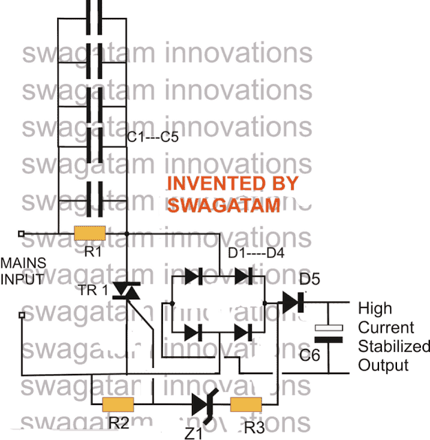
The circuit of a high current transformerless power supply explained here hopefully, effectively handles the surge developing from power transients such that the output becomes free from the dangers, and provides the required current supply at the rated voltage levels.
Everything in the circuit is kept just as its old counterpart, barring the inclusion of the triac and zener network which actually is a crowbar network, used for grounding anything that goes above the rated voltage.
In this circuit the output would hopefully provide a stable voltage of around 12+ volts at around 500 mA of current without the dangers of any accidental voltage or current influx.
CAUTION: THE CIRCUIT IS NOT ISOLATED FROM MAINS AND THEREFORE INVOLVES HIGH RISK OF ELECTROCUTION, APPROPRIATE PRECAUTION NEEDS TO BE EXERCISED.
UPDATE: A better and a more advanced design can be learned in this zero crossing controlled surge free transformerless power supply circuit
Parts List
- R1 = 1M, 1/4W
- R2,R3 = 1K, 1/4 WATT
- C1----C5 = 2uF/400V PPC, EACH
- C6 = 100uF/25V
- All DIODES = 1N4007
- Z1 = 15V, 1 watt
- TRIAC = BT136
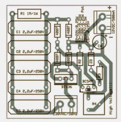
A neatly drawn PCB for the above high current transformerless power supply may be seen below, it was designed by Mr. Patrick Bruyn, one of the avid followers of this blog.
Update
A deeper analysis of the circuit showed that the triac was dumping a significant amount of current while restricting the surge and controlling the current.
The approach taken in the above circuit for controlling voltage and the surge is negative in terms of efficiency.
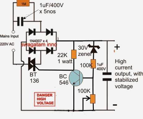
In order to obtain the intended results as proposed in the above design and without shunting precious amps, a circuit with exactly opposite response needs to be implemented, as shown above
Interestingly, here the triac is not configured to dump power rather it's wired in a such a way that it switches OFF power as soon as the output reaches the specified safe voltage limit, which is detected by the BJT stage.
New Update:
In the above modified design the triac may not conduct properly due to its rather awkward positioning.
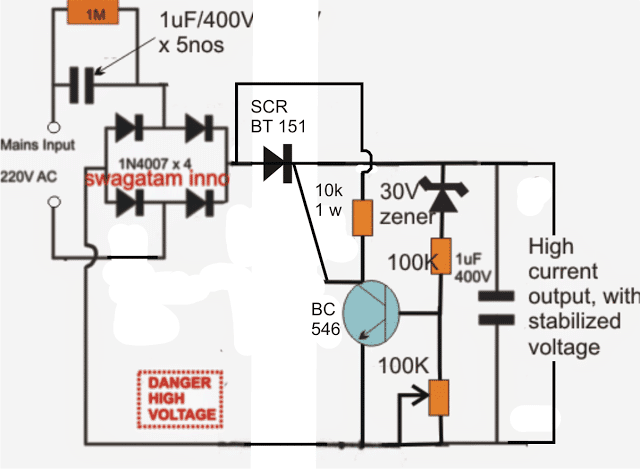
The following diagram suggests a correctly configured version of the above, which can be expected to operate as per the expectations.
In this design we have incorporated an SCR instead of a triac since the positioning of the device is after the bridge rectifier and therefore the input is in the form of a DC ripples and not AC.
Improving the above design:
In the above SCR based transformerless power supply circuit, the output is surge protected through the SCR, but the BC546 is not protected.
In order to ensure a complete protection for the entire circuit along with the BC546 driver stage, a separate low power triggering stage needs to be added to the B546 stage. The amended design can be seen below:
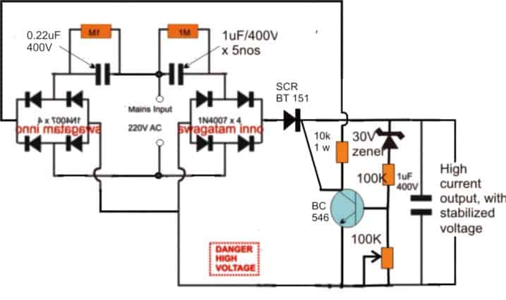
The above design can be further improved by modifying the position of the SCR as shown below:
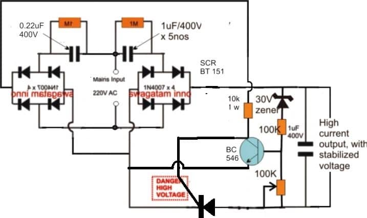
So far we studied a few transformerless power supply designs with high current specs, and also have learned regarding their different modes of configurations.
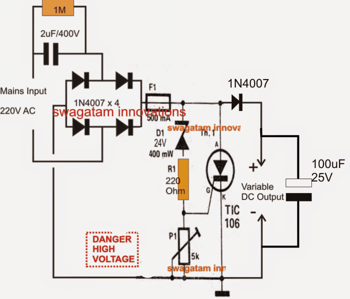
Below we would go a little farther and learn how to make a variable version circuit using an SCR. The explained design not only provides the option of getting a continuously variable output but is also surge protected, and therefore become much reliable with its intended functions.
The circuit can be understood from the following description:
Circuit Operation
The left side section of the circuit is quite familiar to us, the input capacitor along with the four diodes and the filter capacitor forms the parts of a common, unreliable fixed voltage transformerless power supply circuit.
The output from this section will be unstable, prone to surge currents, and relatively dangerous to operate sensitive electronic circuits.
The portion of the circuit on the right side of the fuse transforms it into a completely new, sophisticated design.
The Crowbar Network
It's in fact a crowbar network, introduced for some interesting functions.
The zener diode along with R1 and P1 forms a kind of voltage clamp which decides at what voltage level the SCR should fire.
P1 effectively varies the zener voltage from zero to its maximum rating, so here it an be assumed to be zero to 24V.
Depending upon this adjustment, the firing voltage of the SCR gets set.
Supposing P1 sets a 12V range for the SCR gate, as soon as mains power is switched ON, the rectified DC voltage starts developing across D1 and P1.
The moment it reaches the 12V mark, the SCR gets sufficient triggering voltage and instantly conducts, short circuiting the output terminals.
The short circuiting of the output tends to drop the voltage toward zero, however the moment the voltage drop goes below the set 12V mark, the SCR is inhibited from the required gate voltage and it reverts to it non conducting state.... the situation yet again allows the voltage to rise, and the SCR repeats the process making sure the voltage never goes above the set threshold.
The inclusion of the crowbar design also ensures a surge free output since the SCR never allows any surge to pass through to the output under all circumstances, and also allows relatively higher current operations.
Circuit Diagram
Another SCR based Circuit
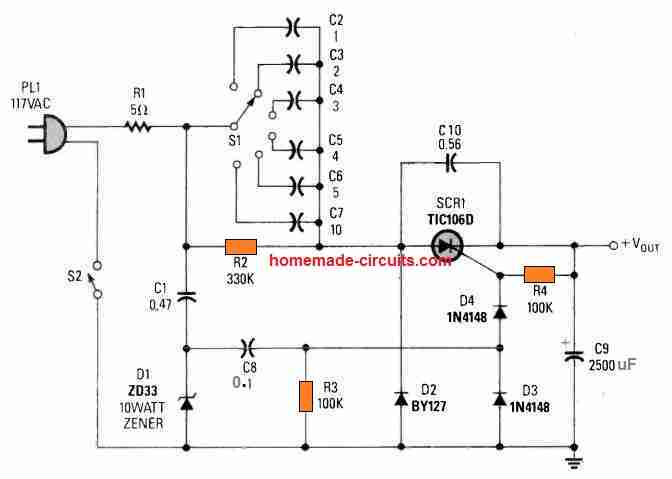
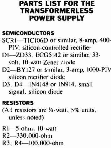
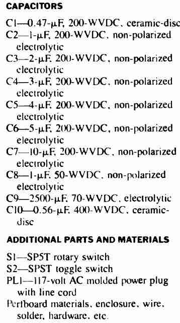
This SCR based high current Transformerless Power Supply consists of rather a few, easily accessible electronic parts.
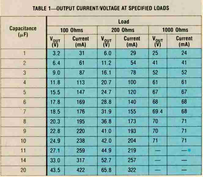
The output voltage level (and also the level of feasible current as provided in the Table I) is adjustable by rotating the rotary switch S1.
Table#1
Zero Crossing Controlled High Current Transformerless Power Supply Circuit
The following circuit shows how a zero crossing concept can be implemented to create an effective transformerless high current power supply circuit, which is highly customizable.
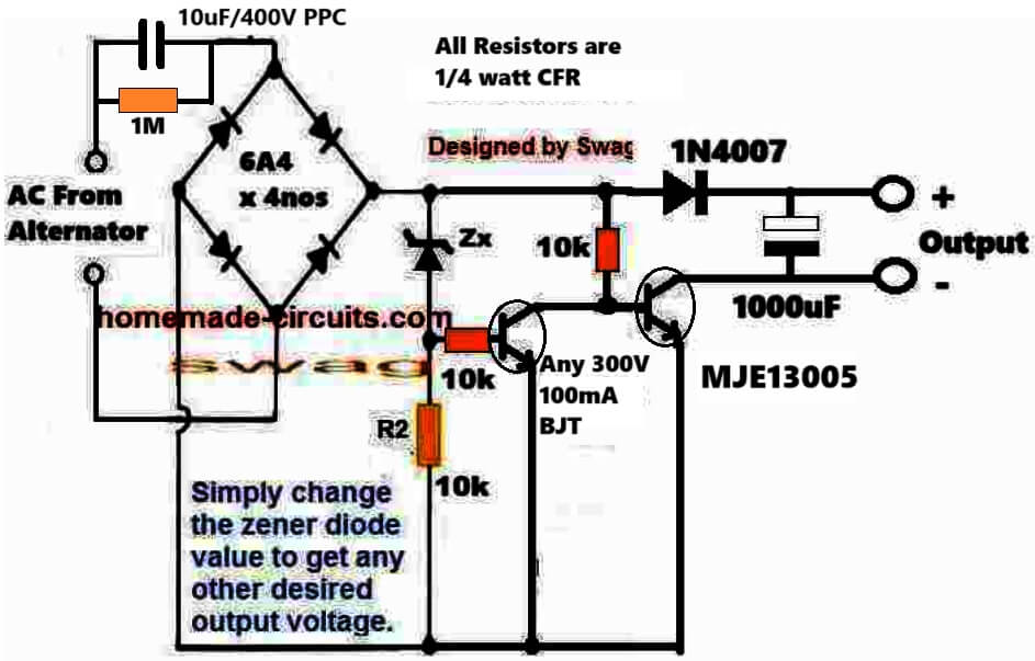
Advantages of this Circuit are as follows:
100% surge free ensures that the load, zener diode and the capacitor are completely safe all the time regardless of the input switching conditions of the power supply.
No heat dissipation ensures that the circuit's efficiency is maximum.
How the Circuit Works
We know that the main issue with transformerless power supply circuit is the switch ON surge current, which happens due to the sudden peak AC entering the electronic circuit connected with the power supply.
This sudden in-rush voltage and current leads to the burning of the vulnerable electronic components attached with the power supply.
This means that, if the load is allowed to be switched ON whenever the AC waveform nears the zero crossing then such mishaps can be avoided.
The above circuit does exactly this.
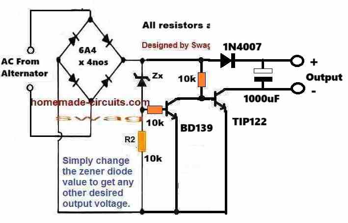
The NPN TIP122 conducts only when the AC waveform is below the zener value.
When the TIP122 conducts the AC waveform is already within the safe range of the load and this safe voltage gets stored in the 1000uF capacitor for powering the load.
The process continues for each cycle and only when the AC peak has dropped down safely to the zener value, which keeps the load powered consistently, with an optimized voltage and current inputs.



Questions & Answers
Swagatam Sir, I wish to make a 15 V 80 A transformerless power supply. Can you help me in designing an appropriate circuit? It is required for solid stat cooling system.
Hi Ravi Kant,
12V 80 amp power supply is not possible using transformerless capacitive power supply concepts, for that you will have to use an SMPS design.
Sir, can you suggest me the circuit for SMPS design for 15 V 80 Amp power supply along with the components.
Hi Ravikant, I will design it soon for you and let you know…
Thank you
I have posted the required design under the following post:
https://www.homemade-circuits.com/how-to-design-customized-220v-smps-circuits/
Hi Swagatam,
Above circuit is intended for stabilized 12DCV, I need 9DCV one, what resistor value to replace for R2 & R3?
Hi Awak,

The first circuit may involve a lot of heat dissipation, therefore I would strongly suggest you to try the LAST circuit given in the above article, which is a lossless power supply:
Thank for response. The 1st circuit is high current one, IINW withstand for about 500mA. What about this one, if the cap I put 5 in parallel, can it be beared the same one?
Yes, it can handle 500mA or more easily because the MJE13005 is rated to handle upto 8 amps. The best thing about this circuit is that the transistor will not dissipate heat unnecessarily.
Sorry to my latest post, try to draw back my comment, but I can’t. A bit mistake read the schematic. It turns out to be have mylar capacitor.
No problem…. yes the 10uF/400V is the one which is mylar…
Swagatam,
I’m just aware, the schema doesn’t have mylar cap like the others, is that so?
Hi Awak, The 10uF/400V is the mylar capacitor.
Ok. Thank a lot.
hello sir. can mje13007 replace tip127 in the last circuit? thanks in advance. ops.. my mistake. mje13007 is npn transistor. but how about changing the pinout? is it posible to use npn transistor in this circuit?
Hello mbahsimak,
The previous diagram had some problems, so I have replaced it with a new one.
Now you can use MJE13007 instead of the shown TIP122….
allright, sir. I’ll be waiting the new circuit. thank you.
The circuit is already updated, please check it out.
one more question, is it allright if i use 4x 1n4007 instead of 6a4 diode?
Yes…and there’s no 6A4 in the updated design:
Sorry, yes the bridge rectifier has 6A4 diodes, which you can replace with 1N5408 diodes if the load is 300mA or above.
thank you, sir. what is the whatage of the zenner diode? I just want to replace a small transformer in portable radio with this one. mybe 300ma up to 500ma 5v.
You are welcome mbahsimak,
If you want to use it with 220V AC then I would recommend having aa series 5uF/400V capacitor with the input AC supply.
And please note that none of this circuits are isolated from mains AC and is therefore carry the risk of fatal electric shock.
zener diode can be 1 watt rated.
allright sir, i understand. but there is not enough place for 5uf/400v cpacitor in the portable radio. is it allright if i just use MB10S smd diode bridge (i can get it from led lamp) without capacitor?
mbahsimak, if you want to use it without an input capacitor then please include a 300mA fuse at the input side, just to make sure nothing burns in case something goes wrong.
sir ,2 phase 415v ac to 190v dc 6amp power supply ckt diagram.
sreenivasulu, how many wires do you have in your two phase system, please clarify this, I will try to help!
Hi sir, I need an inverter circuit that I can use with 0-24v (10amp) transformer
Thanks Majaha, I will try to suggest a proper design for you soon.
Hi Mr Swagatam , firstly I want to thank and praise you for tutorials in electronics engineering, they are very helpful and understandable.I want a circuit for reducing 230v ac to 120v ac(2amps).Looking forward for your response.
Thank You Majaha, I appreciate your kind words.
You can simply use a transformer with 230V winding at the primary, and 120V winding at the secondary for the required conversions.
Hi Swagatam,
do you think the zero crossing version you posted can handle 48vdc @ 1A ? Considering input voltage is 110Vac. Also, should I increase the input capacitor value or can I leave 2uF?
Cheers
Hi Cheerios,
Yes TIP127 is rated at 5 amp 100v, so 48v, 1 amp is within its reach.
However, for 1 amp current the input capacitor will need to be rated at 20 uF/ 250v
Thanks for your reply, do you think is it possible to use smd ceramic capacitors ?
Yes, you can use 20uF 250v smd capacitor if that’s avaliable to you…
What is the maximum current that your final circuit can withstand in its current state without modification? I want to charge an 18650 battery with a current that does not exceed 250 milliamps. Is it suitable in its current state?
Thank you man.
The last circuit using tip127 can handle upto 2 amps, but I am not sure if tip127 is suitable for this application, if it burns please consider using a 400v pnp transistor.
I designed the last circuit as is, without change, and it works very well. I put a zener diode as you did, but the output voltage was 21 volts, so I had to put another 5.6 volt zener diode on the exit capacitor, so there were 2 zener diodes in the circuit, and the circuit actually worked very well. The battery was charged perfectly, noting that the exit capacitor is 2200u 25v. My question to you is: Why was the circuit exiting before the last zener diode was placed? Can I delete the first zeber and leave the last zener? Or leave the circuit as it is with 2 zener diodes?
That’s great Hima, Glad the last circuit is working for you.
Which zener diode did you use at the base of the TIP127?
I think if this zener diode is adjusted appropriately then the second zener diode across the output capacitor will not be required.
Can you please try different lower value zener diodes until you get the 5V at the output.
Otherwise you can also try using many 1N4148 diodes in series to create the intended, equivalent zener diode at the transistor base.
Let me know how it goes.
My dear brother, thank you for your quick response to my message. Firstly, the value of the zener on the gate of the transistor tip 127 is 5.1 volts, but unfortunately it did not work well in charging the battery, and since I combined with your circuit another circuit to cut off charge, it was necessary to add a zener of 5.6 volts for precise calibration to disconnect the battery charge when… Voltage 4.2. Indeed, the integration of the two circuits together was successful, and four different types of 18650 batteries were charged. The charging was also separated perfectly at voltage 4.2, and no part in the two circuits heated up at all. I would like to thank you very much for what you provided on this site. I have another question there. Noise at the ceramic input capacitor. Is there a solution or not?
No problem Hima, if two zener diodes are working good for you, you can keep them as is.
The ripple noise at the input side cannot be eliminated, because if you connect a filter capacitor that will cause the tip127 to switch off permanently and the circuit will not work.
Thank you dear, how much current is the last circuit?
Hello Hima, the current capacity of the last circuit will depend on the transistor current rating, with a TIP127 it can be around 2 amps.
Hi Swagatam!
I must say these articles are very helpful.
I needed your opinion on the following idea for building a high current transformer less power supply.
We design it in two stages. The first stage, is a low current stage which just generates enough power for a small, low-cost, microcontroller with an ADC.
In the second stage, this microcontroller using the ADC and a MOSFET … samples the input AC and disconnects the AC as soon as the voltage goes above say Xvolts and below 0V. So the AC waveform gets clipped and rectified at Xvolts positive to 0V. Then we use a smoothing capacitor to generate the DC we want by changing the value of X in the firmware.
Since the MOSFET is controlled by the microcontroller… it is never switched on above Xvolts … so the surge etc. are all handled adequately.
The point is .. one MOSFET that can handle, say, 200mA of current at 300V, and a small microcontroller are still much cheaper (and easily available) compared to components needed in a high-performance SMPS power supply.
I built and tested this circuit and it works … I am just wondering why it is not used so widely.
Thank you Vineet,
May I know what is the current and voltage outputs of the concept that you built? Can you build a 12 V, 5 amp design using your concept. So that is the actual challenge, building a high current low voltage power supply without involving a transformer.
Let me know your thoughts on this.
I earlier designed two power supplies using flyback switched mode transformer based power supplies for two different projects …
48V 2A for a telecom product4V 600mA for a metering productAt that time I did not focus too much on making them tranformer-less … but while I was validating these designs, I played around with the concept I discussed and it worked. However, I did not invest too much serious time on it then.
Now I need to mass-produce another product and I am seriously looking at using the concept I proposed. But needed your opinion on this before I start allocating resources to it. Can you think of any reason it would not work … so I can think of some way to design better before I ask my team to start prototyping.
The mosfet would turn on when the AC voltage is just zero crossing towards positive, so there would be no stress. There could be some risk that the mosfet would disconnect at X voltage …(say 12V) … but I think since we are using a 300V mosfet … it should not have a problem handling that.
Your proposed concept is supposed to work using a microcontroller and without a transformer. However without a transformer high current generation may not be possible? If you think generating high current is possible, I would be interested to know. According to me SMPS is the only way to transform high AC voltage to a low DC voltage with the desired high current, efficiently.
friend swagatam, I need a transformerless with a stable voltage output of 36 volts dc and amperes 1.5 amperes (in actual implementation it is only 495 milli amperes), is there a diagram above that I can apply?, and what components should I replace in the diagram above so that it can work I can use it, thanks for your attention.
Hi Sudarsono, you can perhaps try the following design:

You can replace the 24V zener with a 36 V 1 watt zener diode and the 220 ohm resistor with a 1K 5 watt resistor. The SCR can be any 5 amp 400 V SCR. The capacitor on the mains AC side can be a 30uF/400V non-polar capacitor. However remember the SCR will get quite hot, that is the drawback of this kind of design.
how to overcome so that the scr is not too hot or becomes hot, thank you for the help, friend swagatam
The heat will depend on the input voltage and the output voltage difference. Since there’s a big difference between 36 V and 220 V, the heat will be also very high, there’s no way to reduce it.
Oky sir,
would you please help me with SMPS circuit which can output 12v at 20amps?
i, have freezing fridge which its power supply was burnt.
Godwin, I do not have a 12V 20 amp SMPS circuit. However, a 20 amp SMPS can be hugely complicated to build at home, so i would recommend you to buy it online which can be quite cheap and extremely efficient.
oky sir,
i, should explain it properly in this way;
as i keep it in mind, a transformerless produces a very low current in (milliamperes) not amperes. What i want is to modefy the circuit to drive 12v 20 amps loads purposes. If you can help this circuit, please present it to me immediately.
thanks,
Godwin.
Sure I understand, however 20 amp is actually too high. I wouldn’t recommend even 1 amp, because even at 1 amp the triac or the SCR can heat up a lot. SMPS is the best way to get a high amp output with max efficiency.
Oky sir,
by ignoring the relay at the ouput of the transformerless, should it be modefied by replacing the STTH600CW rectifier diode along with an inductor?
Godwin.
Hi Godwin,
sorry I could not understand how would you replace the relay with a STTH600CW diode and a coil, and for what for purpose?
Hi swagatam,
i thank you very much, for the work done day and night providing helpfull different circuits. I, Godwin, have benefit from these learning articles keep it on. Now coming to the topic; transformerless with high output current.
sir, my question is, is it possible to include a relay inorder to have high current?(2) and how? If yes, what are the cautions to this? Best regards
Godwin Shonga.
malawi.
Thank you Godwin,
I wouldn’t recommend more than 500 mA in a transformerless power supply circuit. Yes you can use a relay to switch a capacitive power supply as shown in the following example circuit:
hello, i just want to know what the circuit would be for a 230vac to 60dc 10A power inverter in the same way as shown in the design pictures?
Hello, A capacitive concept cannot be used for currents over 200 mA. So for a 10 amp current you might need an SMPS circuit.
Hello Swagatam,
What do you mean by a SMPS circuit please?
The power supply has to be like and function as a transformer and need to be continious.
Like an IGBT welding machine but less complicated.
Hello Willem,
An SMPS is a switched mode power supply, as shown in the following images:
Hi there
My Black & Decker heat gun just stop working and uses a seemingly simple 220V AC board to power a 12V DC (0.284A) motor for blowing the air and activate the heater. So far I have tested the triac and some other parts seems in working order. Could I email the picture of the circuit board so you might advise what component could be faulty.
Thanks
Hi, You can email me, I will try to solve it for you.
Hi Swagatam,
On the Crowbar Network, can I replace TIP106 by BT151, where gate current (Igt) is only 2mA? The zener & potensio which serially installed, are they affected by current through? By meant We can put any components regardless its staying power?
Thanks.
H Awak, yes BT151 can be used in place of TIP106. According to me the zener and the series resistor/pot are not affected by the current because as soon as the zener conducts the SCR fires and grounds the supply, so the affect of current on these parts are minimal.
Thanks for explanation. Here in my city, quite difficult to get 2uF 400V, if I replace with 1.5uF 400V, what resistor to replace 1M ohm?
Thanks.
Sure, 1.5uF will also do but will provide a maximum of 80 mA current output. The parallel resistor can be still 1 M, it is not critical since it is only used for discharging the capacitor whenever the power supply is unplugged from the mains.
Hi Swagatam;
I am having a 220vac / 9vdc unregulated adaptor 2amp output as printed on its body. I need to test the credibility of the output 2amp.
Would you recommend to shunt 4.5 ohm resistance across its output while measuring the output voltage. If it reads almost 9vdc, then it is a 2amp adaptor?
Hi Rezk, the easier option would be to connect a 10 amp ammeter directly across the adapter output for a couple of seconds, and check the reading on the meter. This would give you a quick and a reliable reading regarding the power supply output current.
Thanks…
Hi Swagatam,
I need a simple regulated & protected transformerless power supply 220VAC/1.5VDC-2 amp, will be used for a gas water heater ignition unit instead of 1.5v battery which depletes fast. I tried several 1.5vdc adaptors available in the market, yet they are either below capacity or does not work long & fails due to high amps needed.
I have seen several circuits, but most are below 2amp output.
Thanks…
H Rezk, transformerless power supply using capacitor at 2 amp current can be dangerous and is not recommended, and also it will be very inefficient at 1.5 V, therefore only SMPS is the recommended option
Thanks Swagatam, I will go for a transformer power supply & add an LM338 regulator.
Welcome for any comments.
You are welcome Rezk, that sounds much better!
Sir,
Can we achieve 12v 2Amp Output with that circuit by increasing capacitors?
or any another solution would you suggest which should be transformer less?
Hello Hafiz, 2 amp can be achieved but the triac may get very hot and waste a lot of energy, that is why an SMPS is always a recommended design instead of capacitive power supplies.
Hi Swagatam,
I use 24V batt for circuit trial up purpose on SCR BT151 circuit above, but the SCR is not triggered using 10K resistor, what suitable value to trigger the SCR? Any formula to calculate SCR gate resistor?
Thanks.
Hi Awak, In that case you can try reducing the 10K to 4k7 and see if that triggers the SCR. I do not have the formula in this website, however, you can refer to the triac concept, and deduce the formula accordingly:
https://www.homemade-circuits.com/triac-circuits-working-and-application/
I have already put in live the circuit & measure output side – without load – that is 245V max & 215V min. I don’t brave yet to put a load where I’m not sure what voltage the actual output is. Base on your design, what is output voltage for this built up circuit?
Thank you.
The output voltage must be equal to the zener diode value. If it is not as per the zener value, then something maybe wrong. Or you can put a 220V load such as a 220V led bulb and check the response
Hi swagatam long time havent mail
Any how your help if possible you can design a battery charger
Your transformerless is ideal
My input 380 to 400vac 3phase and output to 12vdc 12 to 30 amp .
Your is very good in my project which a 3phase 380 to 400 vac output thanks
Hi Sean, thank you very much for your kind words! However, I don’t think 30 amp may be feasible with the above explained circuits.
Happy and Very well thank you.. in your response…….
Your are amazing I am impress
Thanks for your talent continue your cool
Hi,
As above circuit which has 5 nos capacitor can handle 500mA, is it possible to reach 1000mA with 10 nos parallel capacitor? If so, any specific calculation for it?
Thank for answer.
Hi, for the first it is not recommended to increase current to 1 amp, or else the triac can get very hot….instead you can try the second concept and see how it performs….
by the way 5nos of 1uF capacitor in parallel will produce 250 mA current not 500 mA.
Hi
I have some AC led strip lights. They run off a small sealed power supply that provides 200 volt DC. The strip lights consume 18.5 mA per meter (they include current regulating resistors) and were sold in 50 meter lengths. ~1A per 50 meter reel. I have been cutting up these water proof strips and using them for the garden path. I would like to make some extra power supplies as I will end up with more sections of led that power supplies.
I had thought that a bridge rectifier with filtering capacitor would do, and to drop the voltage with voltage divider resistors but the power rating of the resistors seems rather high- a zener would have the same problem. Of course I could put many resistors in parallel, but I guess I must be doing something wrong, because the power supplies that come with the lights are very compact, so there must be an easy way to do this.
Anyway any help you can offer would be appreciated. At least if you can steer me in the right direction. I had thought to cut open one of the power supplies to see what is inside, but this will ruin the power supply and I do have enough already.
Thanks in Advance
Choga
Compact power supplies are mostly SMPS and isolated from mains AC, so they are not easy rather much complex to build. If you wan an easy option then you must go with iron core transformer based power supplies and use a 7812 IC for providing fixed regulated voltage to your 12V LED strips.
Hope this helps you! Feel free to ask if you further doubts
Hi,
First of all sorry for my bad english, i’m from Brazil and i’m trying to do my best to make sure you understand my question.
I’m using the HLK-PM01 power supply for a switching circuit with arduino uno, like lamps, low power consuption circuits (TV’s, routers, etc.) and i need this circuit to be smaller. I want to try the transformerlees power supply but i need 5 V 600 mA output, with 100-240 V input. With the solution you show above, can i replace it in my circuit?
Thanks in advance for your attention.
Best regards
Hi, I think the following concept will suit your requirement better. The design explained in the above article may dissipate a lot of power.
https://www.homemade-circuits.com/220v-smps-cell-phone-charger-circuit/
Thank you very much
Also, since i need to be smaller, i’ll try to make that with smd components, using the MB10F bridge rectifier
Hi,
Why cant we use a MOV upto a rated voltage instead of crowbar network.
MOVs are not designed for handling continuous current shunting, they are designed for occasional shunting of few milliseconds.
Hi! Mr. Swagatam
I have read many portions from your site Homemade circuits. My LED TL was not working, I checked and found all LED are working driver is not working, just changed main capacitor but it did not work. Then I connected it through one bridge diode ckt in series with 104J400v taken out of driver & 10 ohms in series and 100 mfd 100v on output of bridge connected to LED series. It worked but light is less then driver connected LED
It is not big matters I can just buy another TL which is only 260. My time is more on making ckt etc but do not understand what driver ckt do why direct ckt as above is not that good
I am 70+ now left electronics for sometime, mainly it is curiosity to know all this
Can you suggest any website where I can read working of circuit
Thanks and regards
Harmahendra
Hi Mr. Harmahendra, the trasformerless supply explained above and elsewhere are all good when correctly calculated with regard to the load, expect that these not isolated from mains and therefore prone to lethal electric shocks.
If you can provide the specifications of the LED, I’ll try to suggest a suitable driver circuit for you.
I just loved ur enthusiasm and knowledge, i just came to say keep going high do something very great for country and society with ur knowledge and work, im sure u will. God bless u.
Thank you very much, i appreciate your thoughts, and God bless you too!
Hello, it is helpful to me. Can you please help me to design transformerless 12V 5Amp power supply. Can i use above circuit ? Which component values i have to change ?
A compact 12V 5 amp power supply can be built using an SMPS only, no other method is recommended.
https://www.homemade-circuits.com/12v-5-amp-transformerless-battery/
Ok thanks for the reply.
hi swagatam,
i want the output of 5v 500mA dc. which is circuit is suitable to my application. what is the protection at input side (AC) if there is any voltage surges?
thanks for sharing your reserch document.
Hi Vamsi, you can try the first circuit from the following article:
https://www.homemade-circuits.com/how-to-make-led-bulb-circuit/
It has all the required protections
Hey Swagatam,
I am fascinated with the way you document and keep experimenting.
Thank you Anand.
Hi Swagatam
what is the highest capacity of this circuit i mean voltage and current wise???
can it supply 30v-5amp ?????
Hi shuvam, highest capacity will depend on the input capacitor value. 5 amp is possible.
Hi Swagatam
approximately which value of capacitor should i use??
And if i use this circuit instead of SMPS will there be any problem???
Hi Shuvam, this circuit should not be used for currents more than 500mA
Hi swagatam,
I have build a circuit using diode rectifier, 105j400v, 1M, 50E, 12v zener and 10uf capacitor for converting 220 VAC to 12v. But the output power is too low to make the board run after assembly. I am looking for a solution to convert AC to 12v 300-400mA.
Please help me out in solving this.
Hi Bharath, 105 capacitor will only produce around 50mA current, so to get 300mA you may have to use around 7nos of 105 caps in parallel, also please reduce the 50 ohms to 5 ohms so that current is not dissipated by much.
Good day Sir. I really need to thank you for this educational information.
I want to build a relay circuit that can be power on by a single push button. Press once, it power “ON” the relay and second press, will power “OFF” the relay. The circuit can be powered by a 5V or a 12V power supply.
Thanks so much
Thank you Elvis, you can try one of the circuits presented in the following article
https://www.homemade-circuits.com/build-these-simple-flip-flop-circuits/
hello,
i wanted to build a 5V, 5A rectified circuit. could you please suggest me the proper circuit diagram
Getting 5V 5A from 220V mains will require an SMPS design. here’s one design which you can try:
https://www.homemade-circuits.com/12v-5-amp-transformerless-battery/
the 12v can be changed to 5V by adjusting the feedback zener diode and the secondary winding
I want to build a 12V, 1A capacitor power supply. Can you suggest an efficient circuit diagram. Thanks in advance.
Hi, The second last diagram in the above article is an efficient design which you can try!!
Hi Swagatam,
I’m also an electronic entrepreneur with similar passion what you have. Thanks for all your efforts so far. I’ve been referring to your circuits for more than 8 years now. I have a question though.
Is there a way to derive 5V, 150mA current to drive a 5V sugar cube relay from mains? And this time, it is not 220v-neutral, but i want to step down 2 phases – 440v (2 out of 3 phase AC mains input) to 5V.
Also, the work is with 3 phase AC input without neutral. I tried all options before reaching out to internet.
Any thoughts?
Thank you Vinay, Glad to have a dedicated reader like you!
You can use the earthing line as the neutral and use any one of the 3 phase lines as the phase, this will solve the problem quickly, otherwise it can be a bit complex.
You can use a spare mobile charger for this and use its output for driving the relay.
Let me know if it is favorable to you, or if you prefer the other complex method.
Thank you for the prompt response, Swagatam.
I dont want to use the earth line, as its failure may cause the panel to give out a shock.
All these days – i think i’ve tried most of the options and i understand more deeper into it.
Instead of using a relay, i wanted to trigger the load using a triac so that the relay coil current can be drastically reduced. However, i was informed that there is no availability of X2 capacitor for 440v AC to connect in series to use in a transformerless power supply. Hence i’m stuck there now.
Vinay, you can try putting 1uF/600 on each phase and terminate the ends with a 3 phase bridge rectifier, then connect the relay coil at the positive and negative ends of the bridge. This will do the job according to me.
Thanks for the inputs. Let me check that out, and update you back here. 🙂
No problems 🙂
Hey There..!
I was making an IoT project for which I needed a Lightweight, small sized power supply.
So, I chose to use a Transformerless Power Supply but I am confused with its current ratings. I need 5V 3A max output from the supply. What components do I choose..?
Hi, I won’t recommend a capacitive power supply if the current is as high as 3 amps. Moreover the design won’t be isolated from the mains and therefore can be too risky. So, You must go for an SMPS according to me.
Dear sir,
I would like to assemble a air cooler using 12 peltier modules. Instead of feeding tec1 -12706 with 12v 72amps, I would like to connect them in series with an input of 144v dc 6amps. For this, I tried a halfwave rectifier and a smoothing capacitor of 400v 1000mfd.
As per calculation, the dc output would be 240*0.5*1.414=169v. But I am getting about 340v with no load and 300v with a load of 2amps.
Kindly suggest a solution as to how can I obtain 110-120v dc from the mains with current output of 6 amps
Dear Shivakumar, even with a single diode half wave rectification, the peak voltage will be 310V, and this will be stored and sent back to the load from the filter capacitor, and therefore you will always see a 310V at the output.
if you remove the filter capacitor then the meter will show 120V, but still the peaks will be 300V, which can be dangerous for a 120V load.
To solve this you may have to use more devices in series so that it works with 300V DC or use a transformer for stepping it down
Thanks Swag
I will try this circuit and give my feedback
you are welcome!
Dear Swag,
This is regarding your second upgrade (the third diagram above)
What is the purpose of 10K 1W resistor connected between the anode of BT 151 and the junction of the collector of BC 546 & the gate of BT 151?
In fact, I tried this circuit. But the said resister is getting heated. What may be the reason?
Thanks in advance
Hi Nirmal, it provides the gate triggering voltage to the SCR. You can try increasing its value to 22K and see if that still allows the SCR firing comfortably…
Dear Swag,
I replaced 10K with 22 K 1W, but still it gets heated up and I also noticed failure of BC 546, three times.
Actually I am new to transformer less power supply circuits. So, I would like to know in detail how the circuit BT 151, 10K (22K) 1W resister, BC 546, Zener and the two resisters at base of BC 546 controls surge and voltage.
Thanks,
Dear Nirmal, the output is protected from surge because the output voltage is never allowed to increase above the selected zener value. The moment output level tries to go beyond the zener level, the SCR is switched OFF by the BC546 preventing the voltage to rise any further, conversely as soon as the SCR is switched OFF the output voltage is cut off which switches off the zener and BC546, switching ON the SCR and restoring power.
But the BC546 may not be protected from high voltage so this will need a separate protection circuit, I’ll try to update it soon…
Thank you Swag.
Hi Nirmal,
I have updated the diagram, please check it.
Purpose of the 1uF 400V cap at output in the last update.
It is positioned to absorb possible high voltage spikes entering the output side
Thanks
Thanks
Dear Swag,
Can I use BTA06 6A 600V TRIAC in place of BT151?
Yes you can use a triac also it won’t have any negative effects…
hi sir for the similar kind of circuit in am getting 30 ma current output i am using the 105j(1uf) capacitor but i want to drive high load so i need more than 500ma is it better to add another 4 r 5 105j caps in parallel to each other
Hi Sanjeev, yes you can add more capacitors in parallel to get higher current, each 105 capacitor would give you at least 50mA.
but make sure to add the triac controller as explained in the above article to control surge currents, and regulate voltage.
hai sir
Can you please suggest me a circuit for making 50v 10amp power supply
ok sir thank u
Hi Richards, you mean using the above concept?
hai sir
No sir, I am using.
Is above circuit works to produce 10amps of current.
Richards, for 10 amps you must use a transformer, the above concept may work but is strictly not recommended…..
you can try the following concept instead
https://www.homemade-circuits.com/2012/01/how-to-make-versatile-variable-voltage.html
Sir, how much power a transformer with the following specs can give ?
230/14-0-14 5A
Will it be 14×5=70 W or
(14+14)×5= 140 W ??
It is 70 watt
hello sir i want to switch 12v dc relay, using capacitive power supply but my zener diode is become over heat.
so please solve my problem..
Hello Devkaran, for a relay you won’t require a zener, you can connect it directly with the DC from the capacitive output…the relay coil is much stronger than a zener and will be be able to regulate the capacitive output safely without any external support. you can use a 105/400V caapcitor for the capacitive power supply
can i replace bc546 with bc548 transistor
and bt151 with TYN612M SCR.
ok sir thank you very much for this help.
you are welcome!
No that won’t do, BC546 cannot be replaced with BC548, and BT151 is specifically recommended for this design
thanks for immediate reply sir,
but i am controlled the relay using pic12f675 micro controller. so micro controller have need pure dc and exactly 5v because i am using adc function and there is need to 5v .i am using 7805 voltage regulator for 5v.
OK, In that case you can use the 7805 for supplying the MCU, and connect the relay positive side directly with the capacitive bridge output.
I hope you have understood the configuration….and also be cautioned regarding the dangers involved with a capacitive PS
hello sir the system is performing but my bc546 has blown up and now going to replace with another and will update you. thanks
with 10K resistor in series the BC546 shouldn’t have blown, anyway you can try connecting a 15V zener between the gate of the SCR and the emitter of BC546, this will hopefully solve the issue..
hello sir i get a fixed voltage of 5v at the output. the 1M resistor fixes it to give only 5volts yet i want 14volts at the output
Olupot, the 1M has no relation to the output, the current will pass through the input capacitor, the 1M is only to ensure correct discharging of the capacitor when the circuit is unplugged from the mains….
you can try the following concept if you are finding the above difficult.
https://www.homemade-circuits.com/2016/07/scr-shunt-for-protecting-capacitive-led.html
Many thanks for quick and clear reply dear Swagatham.
you are welcome Anil!
Hi Swagatham
I will use TL431 based voltage regulator with power transistor for high current handling.
I have seen many rechargable tourches, Emergency lights, LED display circuits use capacitor based simple powersupply. Those work very effectively without any protection circuits such as SCR, TRIAC, Thermister, Zero-crossing circuit….etc. So, is it neccessorry a surge/spike protection circuit…..? If, yes, which circuit would be morethan 75% effective. Just provide link of that circuit.
Probably, it should be Zerocrossing circuit.
Thanks in advance.
Hi Anil, emergency light circuits use capacitor based power supply for charging battery at a very low current rate, therefore the protection stage is not included, still they do use a zener diode for regulation.
you can use power transistor also, but a single SCR or triac handles everything perfectly and reliably, without depending on any special ICs or costly surge protection devices, and a SCr/triac suits better for high voltage circuits than power transistor.
for zero crossing concepts you can refer to this page
https://www.homemade-circuits.com/?s=zero+crossing+power
Hi Swagatham,
I have successfully assembled few capacitive powersupplies for illuminating one or two 20mA leds as nightlamps. I used 474pf, 630V, polyster capacitors. I always use a proper value zener diode at output for voltage regulation.
My doubt, is it suitable, capacitors that use with seiling fan….(usually it’s value is 2.5mfd 400vac) for this type of powersupply….?
Hi Anil, yes it is OK to use fan capacitor also, it is the 400V rating that is important, but make sure that the zener wattage is proportionately upgraded as the microFarad is increased
gud day sir am working on my circuit but i got some things i want you to clarify
1 the orignal circuit had a 100uf/25v and yet this circuit am making has a ppc rated 1uf/400v at the output so i need some help there.
2 what is the function of the 100k pot thanks alot
Hi Olupot, 1uF/400V is not necessary, you can replace it with a 100uF but make sure the voltage rating is twice of the intended output level.
100k pot can used for raising the output voltage to higher limits than the zener value.
good morning sir i apreciate the good work you do thanks alot. i have a question regarding the circuit is it possible for me to increase the output current to around 800mAand also can i use it to charge my small batt of 12v 7Ah.
Hi Oluput, that may be possible, but the triac can get immensely hot, you a replace the shown 1 amp with a 3 amp triac, then it would be fine.
yes you can use it to charge a battery, however the above concept is not isolated from mains, therefore touching the wiring with hand can give a fatal shock…therefore it's not recommended for such applications which may not be covered.
hello sir thanks for the great work. i take time to study each and every circuit you post that i find am in need of.so i have some question regarding this circuit
1. can i get up to around 800 to 900mA from the circuit.
2. is it possible to use this circuit to charge a small motorcycle batt of 12v/7Ah. i wil be greatful if i get it done for my small work bench thanks have ablessed day
Thanks Daniel,
yes you can use it to charge a battery, however the above concept is not isolated from mains, therefore touching the wiring with hand can give a fatal shock…therefore it's not recommended for such applications which may not be covered.
Please answer my query….
The word "below" was mistakenly mentioned, it should have been "above"…I have corrected it and also posted a new modified and technically more correct version of the same. you can check it out at the end of the post.
The opto coupler version is not updated because an opto could make the design unnecessarily complex and an overkill…
Referring to your article
"In order to obtain the intended results as proposed in the above design and without shunting precious amps, a circuit with exactly opposite response needs to be implemented, as shown below:""
their is no circuit below these lines??
someone in comments referred to circuit with optocoupler ,but in this post there is no cct involving optocoupler…..
please point out the updated circuit resulting high current and stable voltage…….
thanx in advance……carry on the good work.
In order to obtain the intended results as proposed in the above design and without shunting precious amps, a circuit with exactly opposite response needs to be implemented, as shown below:
where is the cct in article ?? there is only one cct under update heading???
which cct is the right one ,and will not dump amperes…..??
obviously, the circuit design shown under the update is the one which is being discussed in that section.
both are correct it depends which you feel is better.
what ampere in trafo 220vac? and out ?
Hi Swagatam!
Have you tested that last circuit with the BC546? because I took a look at it and thought: "the triac is iniatially not conducting, to conduct I need a pulse on it, and to have a pulse with some enough current to make it start conducting, I need that current flows through the diodes bridge, but how this could happen if the triac is not conducting? It seems that I need to give a "little push" at the gate's triac in order to it start conducting and after that have my BC546 in open state and therefore applying the collector voltage and consequently a current flowing through the triac's gate".
The point is, there is no current flowing through the circuit at all until the triac starts conducting, but is depends on the circuit ahead it and the circuit ahead the triac depends that triac starts conducting… At programming we call that deadlock…
thanks Swagatam!
Yes, maybe it could not work, I will simulate both approachs at proteus and I come back to you to let you know the results. Thanks again!
however the above issue could be corrected by adding a high value capacitor instead of the 1uF shown at the output side of the design….
thanks thiago, s push button with MT1/MT2 might not work because at the first zero crossing the triac will tend to switch OFF, shutting of the whole circuit.
a capacitor or a 1K resistor as suggested by me earlier could be the only solution.
anyway you can try both the solutions and see which one works more appropriately.
Or two push buttons, one in parallel with MT1/MT2 in order to give that little push I commented and turn the power supply on, and another one in series with the gate in order to cut off the pulse on the triac and switch off the power supply. Maybe it could be a nice solution.
I liked very much your design and I think of implementing it with what I said. I don't want to have a transformer on my project…
Thanks again Swagatam!
Hi Thiago, the last circuit is just a suggestion, it has not been tested by me yet.
yes, to initiate the BT136 some form of arrangement would be required, you can connect another 1uF/400V in parallel with the triacs MT1/MT2 or a 1K 1/4 watt resistor also could be tried.
hello
i want to drive 12vRelay @ 30 ma with this method . Also want to add MOV .pl help which value of MOV i go with ? .
the above circuit won't be required, you can use the following simple design
https://www.homemade-circuits.com/2011/12/cheap-yet-useful-transformerless-power.html
replace the 50 ohm resistor with a 5 OHm NTC themister
Is it possible to light up 20 watt led with this circuit?
it can be used
To convert it into 5v power supply do we need to need to replace only the zener diode or some replacements are required too?
only the zener diode will need to be replaced
Hi 🙂
I want to make 12V 2A transformer less power supply. can u help me? please.
because your given circuit doesn't provide much current.
Thank you
Hi, for 2amp a capacitive power supply is not recommended, you may have to build an SMPS for that
can i use this circuit for laptop adapter(20V,5.0A)
NO…
sir what is efficency of above ckt and how can we increase it???
Not sure, did not calculate it.
Hi,
Its possible to get 0-400VDC of 2A ???
Hi, it is possible, but for 2 amp the triac will need to be rated at 6 amps
Hi,
How can get high voltage (0-400V) with 2A current ?
Hi Swagatam,
Im just starting to find/search for a small low cost PS for driving ESP8266 boards, where the requirement is 5V or 3,3V with 350-500mA and found that your site have the most info about these transformerless PS, but I am confused after looking at all the differet diragrams on your site, so my questions is you have such a diagram on your site and can send post the link ? .. if not, which diagram will be best and what changes are needed ?
thx in advance for your support.
PS input would be 220Vac – 50hz
Hi Allan, I think you should try the following design:
https://www.homemade-circuits.com/2014/02/220v-smps-cell-phone-charger-circuit.html
Dear Swagatam Majumdar,
Greetings !!!!
I need 5v 1ahm output AC to DC transformer less circuit, if you can make this circuit in past, please send the details following email id :
mu2003777@gmail.com
09586516661, 09898586746
i am waiting for your answer !!!!
Dear Mahesh,
for 1 amp current it is advised to go for a SMPS design as explained in the following article:
https://www.homemade-circuits.com/2014/02/220v-smps-cell-phone-charger-circuit.html
Dear Sir,
If i change the zener diode to 15V, do you think the voltage will follow, how about the current? how much current it will give? the current will depend only to the zener or to the 5x capacitor in the input.? thanks
odie
Dear Odie,
yes the output voltage will change according to the zener value.
current will depend on the input capacitor value.
Sir is this your finalized circuit for the high current transformerless power supply
3.bp.blogspot.com/-Y7aCY8rtB44/U_cx5MAANjI/AAAAAAAAIDE/Xj–z257fYU/s1600/efficient%2Btransformerless%2Bpower%2Bsupply%2Bcircuit.png
i am getting no dc output from this circuit.. how can you trigger the traic with a DC control signal without using an optocoupler… and please tell me how to configure the circuit to get the output voltage
RT, a triac can be fired from any DC source, an opto coupler is used only when the triac stage needs to be isolated from the DC stage, otherwise it is not essential.
please check your circuit carefully there could be some mistake in it.
Have you verified the circuit? Please confirm.
Thanks.
Ok..sir,
Thank you..
you are welcome, you can also think about becoming a paid contributor to this site by submitting circuit related projects and concepts…..
Oh, sorry sir, actually at first I could not find your answer….
But sir,
is not possible to make transformer less 15V, 3Amp DC power supply ?
Narottam, transformerless can be in the form of SMPS, capacitive type is not recommended for such high current…the best is transfomer type which is the most reliable.
Sir,
I want to make 15 volt, 3 amp DC power supply in this process for giving the power supply of the project of "wireless cellphone charger" please help me with your advice that which components or value of components will be the change fo making it ?
And one more question, here the wattage of the resistor R1 is 1/4 watt, is it sufficient ?
Narottam, I have already answered it please check the above comment.
Sir,
I want to make a DC power supply of 15 volt, 3 amp for the project of "Wireless Power Supply".
So please help me with your advice that what components will be the change for making it and which circuit is the best for this ?
And one more question, here the wattage of the resistance R1 is 1/4 watt is it sufficient ?
Narottam, you can make it by using an LM338 IC, you can easily find the circuit idea in the datasheet of the IC, or even in this website itself….you will need a 0-24V/5amp transformer for supplying the input to this IC regulator circuit
R1 is only for discharging the capacitor when the circuit is being plugged out of the socket…higher wattage is not required…1/4 watt is enough, moreover the value is 1M that's too high for any possible damage.
Hi Swagatam,
Based on this article How much current it will produced? Is the circuit is been tested? and what type of capacitor you used for this paralled caps.
Thanks & more power to your blog
Hi Odie, it can be used for generating up to 500mA without much heating of the triac…it's a tested design
all the capacitors must be metalized polyester type..
hi,
can i used electrolyte capacitor in series, with inverse polarity each other to substitute non polar dropper capacitor in your circuit, let say i use two 2.2uf/400V elco , arrange in series with opposite polarity
you can try it, technically it should work, but PPC type of capacitor is normally recommended in such applications.
Dear sir,
I want to makr a transformerless power supply to gain 12v 1-2A DC.
Please help me sir how can i do it…
Thank you..
Dear Malay, you must go for an SMPS based circuit instead of a capacitive one, which is never suitable for such high current applications.
Hello sir,
I want ti make a 12V 1-2A output,transformerless power supply.
Can you please help me sir how do i do this.
Hello Malay, you can try any of the designs presented in the following article:
https://www.homemade-circuits.com/2012/03/how-to-design-power-supply-simplest-to.html
how to converted 1amps please update sir
use 15 nos of 1uF/400V caps in parallel at the input and use a 6amp triac
Hi Mr. Majumdar,
Can I use this circuit for three phase input supply.
Input voltage will be ~440V, which will be phase to phase.
Hi, that's cannot be possible, any AC input higher than the zener voltage should work.
remove the triac connection and check again…
hai i made the above circuit its working fine but the problem is when i connect 110vac its not working can you tell me the reason .
yes any phase from the 3 phase can be used with the above design….neutral may not be required. but I am not exactly sure about it? you may have confirm it practically.
Thank you sir.
I have one query. There will not be any Neutral line. Input will be any 2 phases. i.e RY or YB or RB.
So is it possible.?
Hi Vikram, it could be possible if all the vital components are rated at 1kv or at least 700V
Can i use the above circuit for building a cell phone charger which will give 5V and 2.2A of current??
technically it may be possible, but strictly not recommended because the above design is not isolated from mains and is too crude and dangerous to be used as a cell phone charger
dear Swagatam,
it's good AC-DC converter. Can you explain more details transistor, triac stage?
when circuit work normally, current through zener, 100k resistor and 100k variable resistor about 10mA, voltage at base of NPN transistor about 1V cause open transistor. Therefore, voltage at G gate of triac about 0V, triac off => it's not logic, am i wrong??
hope your help!
thank you.
you are welcome dear Ngan!
dear Swagatam,
Thank you very much, you're so enthusiastically.
I understand now.
dear unknown, actually there should be a 1K 2 watt resistor across the triac MT1/MT2….so when power is switched ON, the circuit will switch ON with a low current via the 1K, and switch ON the triac for a full conduction with the rated current of the capacitor….however as long as 30V is not reached the transistor will not conduct, but when this happens the transistor will conduct and cut off the triac…this sequence will go ON very rapidly at microsecond rate, making sure that the output voltage never exceeds the 30V mark or above the zener voltage mark.
Dear Mr Majumdar,
Your electronic skill is superior. Thanks for showing everything with diagram.etc. My question is:
Do you have a schematic diagram of a transformerless power supply 220v AC in. and 3.3v 400mA DC out?
Thanks in advance Christer
…By the way you can simply use you mobile charger for the purpose by adding a couple of 1N4007 diodes in series with the positive to get the same…
OK, in that case the following SMPS design could be recommended:
https://www.homemade-circuits.com/2014/02/220v-smps-cell-phone-charger-circuit.html
the zener at the output can be adjusted to achieve the required 3.3V instead of the shown 5V
a capacitive transformerless power supply could be dangerous, and therefore may not be recommended for your application
Thank you for responding so fast. It is a project for school. Burglar alarm, and I'm using Arduino.
I need to supply with 3.3 v.
Thanks again
Thanks Christer,
May I know for what application you are planning to use it?
Do you think i can use this circuit for the 100W LED's? Because transformer 24V 3 amp they dont have here 🙁
ok, thanks, i am going to try to lower the winding's from the coil.
No this circuit is not recommended for a 100 watt LED module.
Capacitor increase so current increase i am right?????? Explain triac and zener function in 1 st circuit
the triac grounds the excess voltage that surpasses the selected zener voltage level and thus maintains a constant voltage at the o/p
yes that's correct
Hello Swagatam,
Thank you for publishing your design.
I made a PCB design of it with almost identical parts you suggested, but I cannot get it working. Could you please look at my design for what mistake I obviously made?
Thank you in advanvce!
PCB design: https://drive.google.com/file/d/0B8jhrSu-d9NHRVpEV1BhSjBKNzQ/view?usp=sharing
Again I build up this PCB but it just doesn't work. Can anybody take a look at my design and maybe tell me what I am doing wrong?
Thank you in advance!
Hi,
Thanks for your reply.
I change the transistor and the overall layout. Could you guys please take a look if this looks oke?
Link: https://drive.google.com/file/d/0B8jhrSu-d9NHdk56eGd3U0tQNVk/view?usp=sharing
Thank again!
OK thanks, I'll check it and correct it soon.
In PCB by mistake Triac gate is connected with BC547( Emitter ) instead of Collector that is why circuit is not working, if I am not wrong. rotate NPN transistor 180 degree in PCB design software hope it will work.
Thanks very much Patrick, I'll update the info in the above article soon…
Thank you madusanka, for any high watt LED it's always recommended to use an SMPS adapter, however you can also try the following circuit and see how well it performs:
https://www.homemade-circuits.com/2015/05/zero-crossing-controlled-surge-free.html
use 3 nos of 105/40v capacitors in parallel for the input capacitor in order to get at least 200mA current at the output
Thanks so much june1629,
if you are looking for a good surge free transformerless power supply then probabaly you would want to try the following design:
https://www.homemade-circuits.com/2015/05/zero-crossing-controlled-surge-free.html
It's much sophisticated and reliable than the previous ones, but kindly be informed it has not yet been tested by me practically. though I strongly believe that it's technically sound and without any errors.
Hello Sir can i use this circuit for microcontroller based project , i am in search for Mc based fan regulator transformerless supply , will u plz tell me how can i take output for zero crossing detector through it , plz reply soon, Thanks
Hello Tariq, the above circuit does not include a zero crossing detector so I am afraid it might not be suitable for an MCU,
by the way I have a PWM transformerless fan regulator circuit in this site but without using a MCU, you can see it below
https://www.homemade-circuits.com/2014/06/pwm-controlled-fan-dimmer-switch-circuit.html
That was a pretty quick response, i wonder how you must be coping up with tons of queries you might be getting in various threads you've started 🙂
Now, I agree with your response, and was of the same opinion to start with. Well my aim was to try and see if size and weight can be reduced, hence started exploring this alternative. SMPS uses a transformer as well, so i was thinking of going for regular mains transformer 12v 1Amp, with a LM1117 ahead to get the regulated 3.3v as desired. I do understand that SMPS is better, but seems to me to be a overkill for the application. Let me know if you think otherwise. Thanks a ton again !
thanks pushkar,
SMPS concepts utilize a small ferrite transformer and the whole unit could be five times lighter than an identically rated iron transformer. Moreover these are cheaper and much long lasting than their transformer counterparts.
You can buy a 12V 1amp adapter from the market if you find it difficult to build yourself.
LM1117 may not be necessary, just use a 7805 IC to drop the 12V to 5V and then followed by three of 1N4007 diodes to further drop it to 3.3V approximately
Kudos to your work Swagatam ! I'm looking for deriving 12v dc to operate a relay in a wireless switch rated around 150 ma. Also, want to further step down 12v dc to 3.3v dc (precise) for the sensitive wireless circuit to work. Current required is around 500ma here. Is it safe to use a regulator IC like LM1117 to buck 12v to 3.3v in this non-isolated power supply circuit, without blowing the IC off ? Point to be noted here is that, the load is not always present as its a switch, in contrast to the LED load discussions above which is always present. Total load current will vary from 50ma to 650ma peak, which should be managable as per discussions above. Your expert guidance awaited …..
…you may try the following one instead
https://www.homemade-circuits.com/2014/02/220v-smps-cell-phone-charger-circuit.html
Thanks Pushkar, I don't think the above circuit wold be suitable for anything other than LEDs, because a mains shock isolation may not be necessary for LED applications and also LEDs do not require highly sophisticated DC for operating.
Therefore I would rather recommend an SMPS version for your unit and not the above design.
how to increase current in this circuit?
Nitesh, the above circuit may not be suitable either for your application, you can try the following one:
https://www.homemade-circuits.com/2013/02/using-ntc-resistor-as-surge-suppressor.html
Respected sir
i read your artical dimmer in series with capacitor.But it is not suite for me.
pl inform can i run 8mm*60 led ( vf= 2.2 v Toal string current is 30 ma) with update august 22,2014 ckt ? may i use single 1uf/400v instead of 5 ?
thanks sir
a god quality capacitor will never break….use a god quality capacitor as shown below:
for voltage regulation you could try a triac dimmer in series with the capacitor input supply as shown here:
https://www.homemade-circuits.com/2014/11/high-current-transformerless-power.html
i want to run 8 mm led total 50 nos. in series with transformer less smps.
led vf = 2.2 min & 2.5 max. @ 25 ma per led.
But i need stable output with stable in ac voltage spikes & fluctuation.
i used MPP type capacitor but not satisfied due to break di-electric after some time .
no problem with use of triac or any part in with ac line. But ckt must be stable .
remove triac stage and use a fan dimmer circuit in series…then increase the capacitor value as per the required current
Dear Respected Sir,
Can I use BC546 to run 25pcs 150mA LED and 2 pcs 39v Zenor Diode serially in the Second like circuit? What is the use of 1uf ceramic Cap at output? what is BJT stage?
Could you tell me which Transformerless simple circuit is suitable to run 25 pcs of 150mA LED serially/paralleled initial switch on surge protected. I am unable to find suitable circuit in your oceanic blog. I have tried NTC 10D ( 10hom) before bridge rectifier but it is not feeling much warmth NTC after immediate disconnection, post Bridge rectifier serially seems to have not effect of NTC.I used a 225k(2.2uf) Cap and 10uf 250v cap as filter.
Dear Bubai,
Don't use any of the above circuit, instead you can a simple design as shown here
4.bp.blogspot.com/-Ao044-f_094/USJX2xXmq9I/AAAAAAAADLw/QXbrfjnDjHc/s1600/surge+protected+led+driver+circuit.png
….use the second circuit, connect all the 25 LEDs in series at the output of the circuit…and and use a coil in place of the NTC
make this coil by winding about 300 turns of 30SWG enameled copper wire on any ferrite core, or you can use the coil from any old relay for the same but the relay coil resistance should not be more than 100 ohms for good brightness.
Sir,
According to Second schematic LED blown out First switch on 2 times tested.
tested using single 225k(2.2uf) Cap and 36v and 12v zenor alternating result same used 50k pot instead 10k.
LED not lighted completely just a flash and gone but not all 150mA LEDs used.
Let me know how to overcome this problem?
1st Circuit is tested okay really protecting from surge created by Capacitor by delay effect used 470uf Cap.
…in the second circuit please connect a 0.1/400V cap parallel to the triac MT1, MT2 otherwise the triac will fail to sustain its conduction.
Bubai, you shouldn't have connected the LEd directly at the output, you should have first confirmed the voltage by adjusting the pot, and once it was adjusted to the LED level, only then the LEd included.
Dear Sir how can i convert 62volt .30mA ( this is telephone line dc supply ) to 12 volt & .750 mA current please give circuit s about this ,thanks
Dear Bijendra, Volts can be reduced using a transistorized circuit but amps cannot be increased…
so your saying there is no way to build a power supply like that, or should I just assume that they just connected all +24v and 24vgnd's together for the sake of the type of connection used?
yes you are right, just terminate the outputs separately through different wires, that's all….at the most you could use separate diodes for the positives in order to create some sort of isolation.
Or could you just design a power supply than can produce (3) +24v leads and (3)+24vgnd with a transformer…. something that can push about 10 amps i already have a center top 120-12/12 at 5amps transformer
sorry, it doesn't look feasible to me…
Can i use 22V, 1W Zener & TRIAC BT134 ?
yes will do
Why did Triac use for? pls explain…
for controlling voltage and surge current
sir how to increase current at output upto 5 amp? Is this ckt is very safe & easy as use transformer for drive LED? can we use "Universal High Watt LED Current Limiter Circuit – Constant Current Circuit for LEDs" circuit as in your blog on right side of this ckt for constant current generator for LED?
Ashok, capacitive power supplies are never safe or efficient for low voltage DC applications.
You must use an SMPS for your requirement as explained by me in your other comment.
Thanks for your quick reply.
Actually I want to control brightness of LED by using a Potentiometer
Please tell me where to incorporate a POT safely… in this circuit.
Thanks for your quick reply.
you can add the left side circuit given in the following article:
https://www.homemade-circuits.com/2014/07/variable-led-intensity-controller.html
connect the LEDs between the transistor emitter and the negative of the supply.
What will happen if I lower its resistance R3 and or R2
I have lowered R3 to 470 ohm still working….
If you lower R2 too much the triac will stop working.
If R3 lowered too much, the zener and the triac will burn.
I have tried using 475uF 40v Cap in C6 Flickering lowered but a audible sound still there.
Also Please check why Consuming 157miliAmp at 230v AC that is around 36 watt in a Good quality AC Ameter aw well as in mulitmeter selecting AC amp.
I am trying to build a led Lamp for my Planted aquarium with 1 watt or 3 watt LED in RED, BLUE, WHITE Color because I cannot afford imported High lumen High power LED amp.
please try the last circuit shown in the following article, you can expect a much better response from it than the above design according to me, you can try it out.
https://www.homemade-circuits.com/2012/09/surge-protected-cheap-transformerless-3.html
the high consumption in the above design could be because of the triac conduction which shorts the entire capacitor voltage to ground while regulating the output
I have successfully made some LED project from you blog Thanks very much for that. but, in this project though I have not made any mistake arranged according to the diagram checked several times but getting 95 volts DC at C6 terminal output, for a single 225k PF and 15v Zenor.
I used 1pcs 225K capacitor 2 run 1 watt LED 4 pcs serially but flickering also producing audible flickering noise replaced 100 mfd by 475mfd 63v Polarized capacitor visual flickering diminished but faint audible noise still remain. Is BT136 producing sound or capacitor no heat at no components Triac, R2 R3 and 15v 1/2 watt Zenor diode after 8 hours running.
But consuming 156-160 miliamp at 230v AC Adding more 225k 250v PF producing more flickering audible noise as well as current and intensity of led and current consummation.
I have tested this project in Breadboard as well as Vero board found same result. can you explain How can be fixed?
Thanks Prosenjit,
Change C6 to 10uF/400V and check, it's the capacitor that could be causing the flickering noise.
I'll update a new circuit soon in the above article, you can try that if you are having problems with the above.
The cost of PP capacitor is high here in Nepal so using 5 of them is way costly, can you propose another circuit with at least 500mA current?
A capacitive power supply will require many PP capacitors without it you can make a 500mA unit, the best thing would be to buy a cheap reliable SMPS circuit from the market costing just Rs.100/-
Sir Arun again.
All the problems of my circuit have been solved myself.
Now i am in the middle of constructing a wireless audio system.
My intention is stated below:
A blower ( instead of fan ) is placed nearer to TV both sits in the hall of my house. So when i am turning on TV fot entertainment, it would be necessary to increase the volume of TV to overcome the sound from the blower. So i have decided to make a wireless audio control system which is intented to place at a comfortable distance from me and help me in hearing the exact sound as heared from the TV.
It is supposed to take the audo from the audio output jack ( To VCR ) of the TV and let it be processed and transmitted to air by a homemade FM transmitter. Then a FM receiver kept at the other place captures the aired signals and reproduces the original sound signals. I want to include a jack for headset also so that i could enjoy TV at night without disturbing others……
So could you plz help me in starting this project…. I am exopecting your help throughout this project
Congrats on that Arun!
As for the wireless transmitter, I already have one such design in my blog, I have tested it perfectly, it'll give a distortion-free reception in your cell phone FM radio, you may refer to the following diagram:
https://www.homemade-circuits.com/2012/01/how-to-make-wireless-speaker-system.html
Sir, i have to ask you one doubt. This is not related to the current problem. My question is : Any other means exist to step up a 120 V AC voltage to 230 V AC instead of a step up transformer ?? ( like a popup capacitor in a transformerless power supply )
Arun, yes you can do it using charge pump circuits, but the current will not be sufficient.
en.wikipedia.org/wiki/Voltage_doubler
That memory element shown in the diagram is intented to inform us the current status of the overhead tank.The red LED associated with that portion will be turned on once that tank is filled and retains that ON condition for a long time. It willn't be affected by any power failures. So we can get know whether the tank had been filled or not at any time..
It was working perfectly at first weak. But after that, it is not getting turned on automatically when water overfowing detected by the Auto off trigger. But when a power failure occurs after the overflowing detected and current returns, it is getting turned on. I think sufficient voltage is not reaching the sensing node of the memory cell which may be causing this problem… So by the by what z ur opinion abt thz sir ??
Arun, to save time and confusions, send the diagram in parts, i'll try to solve them stepwise
Sir, after a long time i came back again. This time seeking your valuable help in one of my previous project….. I have sent it to hitman2008….
Plz check it and reply me soon sir
Arun I have answered your email.
Sir.
You missunderstood my intention.
I mean ;
Eventhough the sensing voltage is to be taken for the opamp stage , it will get affected by the reference 12 V supply when the battery is under charging and a resulting voltage appears as the voltage for the opamp. Am i right sir?
If yes why couldn't it be possible to feed this resulting voltage to the opamp for sensing ???
In my design, i have chosen the maximum power saving mode for the battery.
If i am feeding the battery voltage as the sensing one, the opamp stage will function always even during discharging period ( which is not recommended ) drawing a current of 9 mA from the battery.
But in my design, i have selected the 12 V rail as the sensing voltage itself since a resulting voltage between this and the battery voltage appears during charging, and this resulting voltage is getting compared till certain cut off. Thereby by my design, no unnecessary current drawings are there from the battery during power failure.
You didn't reply to ma last question.
CAN I MAKE THE CUT OFF POINT BY CONSIDERING CURRENT FLOW TO THE BATTERY DURING CHARGING ( selecting a cut off voltage at the point when the current flown to the battery has been completely stopped ) ??????
Arun, Your circuit is too lengthy, and due to lack of time I couldn't go through it all at once….if possible send it in parts and put the relevant questions there…. I'll try to check them out.
for current sense triggering you may refer to this post
https://www.homemade-circuits.com/2012/05/low-battery-cut-off-and-overload.html
Good morning Sir.
Is it possible to take current flowing to the battery as reference to make charging cut off at fully charged condition ???
Means, considering the current flowing to to the battery from source during charging, and select a threshold voltage level at which the current bcomes zero ( no more current flows to the battery ) as the cut off point.
But when i am noticing the charging of my two series connected 4.66 V batteries, i have found that, initially the charging current rises to a high level ( say 130 mA ) and slowly it is getting reduced . At last it bounces back and forth between some current level ( say 47.2 to 47.6 mA ) it is not becoming zero.
Hi Arun,
the voltage that is been fixed is referred as the reference voltage and the sensing voltage needs to be taken from the battery.
add a feedback resistor 100k from the output of the opamp to pin3 for restricting the fluctuations at the thresholds.
I have covered all these comprehensively in all the 741 battery charger circuits in my blog.
Sir would you mind checking your hitman2008 inbox again ?
THEN AFTER THAT
:-
If i am getting that much current (160 mA ) from that config.,
will it be possible to add several capacitors in parallel with each additional zener diode taken place in the circuit along with a MOV and safety resistance ( for surge protection ) deliver higher value currents ??????
Arun with 8V you eed to connect the parallel LEDs in strings of two and possibly add a 50 ohm resistor i series with each string.
if you add a zener diode ,the current may not increase as per the requirements and calculations.
with low voltage loads a capacitive powers supply will not work correctly ad efficiently.
After checking my circuut i found the following current consumption
For parallel config. Of batteries ( 4.5 V )
1). Current taken from the source to battery for charging 39 mA
2). Current drawn from the battery during discharging is 80 mA (little brightness)
For series config. ( 8.8 V )
1). 39 mA
2). 160 mA ( more brightness )
Since in both cases charging current is same, i chose the series config. because i need more brightness.
Is my selection fruitfull Sir ?
Also i could understand that a single power supply will not deliver sufficent current during charging phase ( 2* 30 mA of a relay + 39 mA for charging the battery + 7 mA for operating the circuit components = 106 mA whereas the 1.5 uF alone can only draw a maximum of 85 mA ).
So could you please tell me whether it is possible to use any combination of two 12 V 1 W zener (parallel or series) could be used in association with two parallel 1.5 uF capacitors in a single power supply. Surge current to be avoided by a MOV and a Surge limiting resistance ???????????????
Arun,
With a low voltage DC source such as a battery, series or parallel connection both will give same consumption and brightness for the LEDs if configured correctly, I dont understand how it is differing in your case…strange.
I could not understand this question:
Also i could understand that a single power supply will not deliver sufficent current during charging phase ( 2* 30 mA of a relay + 39 mA for charging the battery + 7 mA for operating the circuit components = 106 mA whereas the 1.5 uF alone can only draw a maximum of 85 mA ).
If you use zener diodes which regulate voltage by sinking current with a capacitive power supply, it will cause it too become highly inefficient and will drop its current greatly
I think you should use a cell phone charger as the input instead of a capacitive power supply.
Since the power supply is not able to draw above 80mA from the 1.5 uf capacitor and higher value capacitors causing high surge current problems, i have
designed the circuit in such a manner that No two relays activates simultaneously during charging time to avail sufficient charging current to the battery, after charging no current is required to battery so the availablr current is used to activate the two relays effectively. Similarly during discharging time, both relays are idle due to the absent of power supply therby saving the current from battery.
THEREBY I HAVE AVOIDED THE LOW BATTERY CUT OFF BY OPAMP STAGE.
OK got it!
I have replied to ur mail. Could u plz check it out as earlier as possible ????
I have reverted….
SIR I HAVE SENT U A CKT. 2 hitman2008@live.in
Could u plz check it out ? I have some doubts
I have answered it.
Sir,
Could u plz tell me what are the lower cut off voltagr and higher cut off voltage of a portable emergency battery showing 4.17 V
High = 4.66V
Low = 3.66V
Sir i didn't get what u were suggested last time. Could u pls help me in modifying the current circuit by varying DC output using TRAIC BT136 with 24 V zener used
U have already posted based on SCR ( which is having varying 0-24 V DC ). But i need a one based on TRAIC.
If we can modify thz like that, will we get high current ouputs( say upto 500 mA ) like in the current ckt ?
Arun, triacs don't respond well to DC variable inputs so it's better to use a transistor instead as shown in the following article:
https://www.homemade-circuits.com/2013/02/how-to-make-simple-220v-transformerless.html
Just modify a few things in this design:
Provide the input voltage through capacitors
replace D2 with a bridge rectifier.
Make R1 = 10k, 2 watt
and R2 = 10k pot
The zener diode may be completely eliminated.
Sir, could u plz suggest me
4 Hrs ON 20 HRS Off timer ckt with caliberations which can be understood easily ( 4017 or 555 )
Arun, 555 and 4017 cannot be used for getting 20 hours delay, it will give inaccurate results
Sir i have used BT136 instead of SCR. What 2 do now to make that ckt functional ?
And what abt this ckt, regarding the high voltage (40 V ) prolblem ???
try a 6V zener and check the results.
The fig. 4 which i am not getting output is
https://www.homemade-circuits.com/2013/05/variable-surge-free-high-current.html?m=1
connect two 1N4007 diodes in series with the SCR anode and check whether it works or not.
In the intention of getting 12 V output, i have connected a 12V 1 W zener. But the problem is i am getting high voltages ( say 40 V ) even in single capacitor config. What 2 do ?
On checking your High current transformerless surge currentlimitted power supply ckt similar to thz, i didn't get any output
Sir,
You warned me not to use capacitors in parallel in the power supply discussed b4 since it causes high surge currents. Can i use this schematic ?
Or the one in the below link with one capacitor being replaced by parallel config
2.bp.blogspot.com/-z8OiKZpXIvg/UY3rG8dkgMI/AAAAAAAAEHg/9YMwKeEFwPw/s1600/variable+transformerless+power+supply+circuit.png
yes it will work in such circuits but it's always good to use smps designs for getting the correct and efficient results
Hey, I tried and made the same circuit mentioned above, but the problem is that the output its giving is above 250v and I need it almost 50v. How can I get upto 50v??
Can I use 78xx series for the output?
which zener diode did you use in the circuit?
i want to made this circuit voltage output of 30 voltge for glow 10 LED in the series. please tell me i need to change here capacitor or other component.
I think you should try the following design instead of the above circuit:
https://www.homemade-circuits.com/2012/04/how-to-make-led-bulb-circuit.html
I am using this circuit for a 12v 20 watt led, but it is not glowing completely as compared to 12v battery.the output of the circuit is 12v and 0.54Amps.10 watt led is working properly
what can i do for about 30 watt Led,can i use this circuit for 20 and 30 watt Led after increasing the amps upto 1amp?
I wouldn't recommend the above design for operating a 20 watt or higher LEds, it's better to go for an 12V/ 2amp SMPS readymade unit, which would provide a safe, reliable and permanent solution………. and also will be free from lethal mains shocks.
I need to change this circuit into 30v and 18 volt. please tell me how can me made?
use a 30V or a 18v zener for Z1, these will produce the specified outputs respectively.
what can i do for about 50v output..
and how can i increse the amps about 1amp..plz explain in proper manner so i can understand it,i am new in electronics..
thanks, i will try it. 🙂
use a 50v zener at the triac gate, and increase the no. of capacitors until you get the required 1amp from the circuit.
sir it 105 and 1uf the same if yes then it can be use in this circuit Simple Pure Sine Wave Inverter Circuit – 500 Watt Pure Sine sir can 105/400vpp use instead of 2uf or two 1uf? thank you.
yes that's correct, you can use two 105 caps, although it will become very bulky, it will work
sir please can i replace 105/400vpp in place of 2uf/400v can i also use this circuit to power my remote circuit which need 5v supply?
yes you can replace 1uF with 2uF, but this circuit is not recommended for delicate electronic circuits since it's not isolated from mains.
why you have taken zener sensing voltage from dc and grounded it to AC line (through resistors)??
R2 is not crucial, it can be removed, the zener ensures that the triac conducts only after the desired zener voltage becomes available at the output, and thus keeps this voltage constant at the output.
After running the 20W LED with 10uF for more than a month, it fuses suddenly. First LED fused, then C6 bursts (33uF/63V).
The reason I am suspecting:
I was driving another 12V/0.056A fan for cooling from same 36V O/P with resistance driver.
1. First resistance (1W) driver fails, which fails the fan to run.
2. LED get hot and burnt.
3. Peak voltage increased across C6 and it burnt.
Another possibility of damage: The power extraction may be too high and those Chinese LED will be certified someday for its voltage and current 🙂
Next modification I am thinking:
1. to use 30W LED to get 20W power. You will get 30% margin of protection.
2. Stable circuit for fan. 36->12V may be problematic with traditional LDO regulator. How about capacitor divider before rectifier?
BTW, my 3.3uF, 6W (6x1W) is running since last three months 24×7.
-CM
Was your 20 watt LED rated at 36V? In that case the fan wouldn't have done anything wrong, however if your LED was rated for a lower voltage then definitely the application was incorrect.
I think before connecting any LED it must be ensured first that the output voltage exactly matches with the LEd forward voltage.
Sir,
Are you test it…..
Because R2 is getting very hot…….
I am used in R2 1k 1 Watt……
PLZ solve my problem if you have any solution.,……
please don't become restless….the site is all about learning through discussions, experimentation, calculation etc.
Try using a higher value for R2, try a 10k, 1 watt resistor.
hello Swagatam,
can i use this circuit to run a 12V 0.2A dc cooling fan continuously ? if not why? what changes done with circuit, or what V/A rated fan i must use?
hello max,
yes i think you can give it a try. start with a 2uF/400v cap iniially for C1
Yes it may be tried for further reinforcement, with LM317 in its current regulation mode as discussed here:
https://www.homemade-circuits.com/2013/06/universal-high-watt-led-current-limiter.html
Inteersting Info CM! I am sure the visitors would greatly benefit from this.
Actually I am already committed to sharing my exclusive ideas with the readers, if you think you have a better plans for me where you could use my innovations for generating some sort of income for both of us, then who knows I may slowly wind up here and start concentrating on the new job;)
Anyway, thanks a lot for showing your kind concerns! appreciate it.
Thanks friend!
It feels very satisfying when I see readers succeed with my projects!
Yes, I'll be careful about somebody stealing my credentials, I appreciate your suggestion very much!
Many thanks!