In this post I have explained an effective and efficient high current compact LED Driver power supply using a dimmer switch gadget.
In one of my other posts I discussed a high voltage transformerless power supply circuit that used a triac for controlling the capacitive output, however since the concept involved shorting the capacitive output by the triac the design suffered heavy losses and thus lost much efficiency in the course.
The Circuit Concept
Any power supply where a shunting of the output is involved will lose efficiency due to the precious power being subjected to the ground...which is a very crude method of achieving a voltage control.
The correct procedure for achieving optimal performance is to do just the opposite, it is to cut off power to the output as soon as the output tends to go above the specified or the rated load voltage, rather than shunting the output V and I.
Acquiring an optimal current supply from a capacitive power supply can be difficult because a capacitive power supply as we all know work efficiently only as long as the output load voltage rating matches with the input voltage of the power supply, example a capacitive power supply working at 220V will work efficiently only if the load specs are also rated at 220V...otherwise the efficiency of the supply will begin falling and result in drastic voltage and current drop across the connected load.
Therefore when a lower DC load is intended to be operated from a 220 V capacitive power supply and a resistor is incorporated as a straightforward or a cheaper alternative for dropping power, a lot of energy gets wasted in the form of heat and the system becomes unable to work with max efficiency, the same happens with a circuit that shunts output voltage for implementing voltage regulation.
Using a Dimmer Switch for Controlling AC
REMEMBER THIS CIRCUIT CARRIES FLOATING MAINS AC SUPPLY, AND THEREFORE IS EXTREMELY DANGEROUS TO TOUCH IN AN OPEN AND POWERED CONDITION. EXTREME CAUTION IS RECOMMENDED WHILE BUILDING OR TESTING THIS CIRCUIT.
In the present design we make use of a dimmer switch for driving LED lights. As we know a dimmer switch employs a triac for controlling voltage but instead of shunting power the circuit chops the AC into sections such that the average voltage at the output becomes compatible to the desired load voltage.
Chopping the AC into wider or narrower sections as per the required load potential allows the capacitor to work at its full efficiency since the excess power from it is simply cut off instead of shunting or shorting to ground.
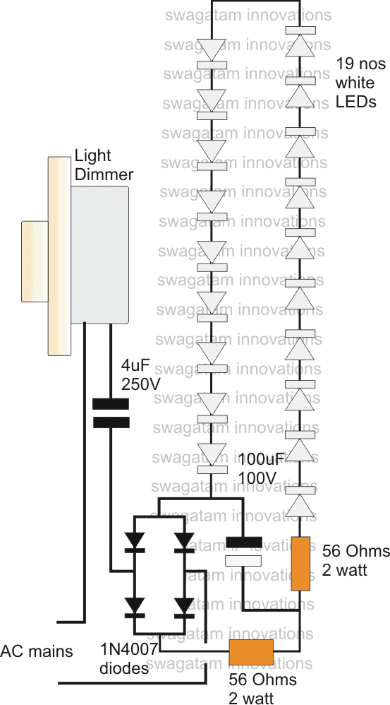
A nice example may be witnessed in the above diagram where a dimmer switch may be seen wired with a capacitive transformerless power supply circuit for operating a high current load such as a string of high watt LEDs.
Capacitor for Controlling Current
As may be seen the capacitor used is a 4uF high value capacitor which may be rated to provide as high as 350mA of current when operated in its max efficiency only as long as the load doesn't shunt or short the power.
The dimmer switch allows the entire high current to pass through the capacitor but restricts the voltage by chopping the AC phase into calculated segments.
The above feature ensures a full 350 mA to for illuminating the LEDs yet prevent the dangerous high voltage from the capacitor to the load in order to prevent the load from damage or over heating....the procedure ensures a perfect efficient operation of the proposed high current transformerless LED driver power supply circuit.


Questions & Answers
How to build this light dimmer switch…
Dear Sir,
I am in need of EHT No.8-598-845-00 for Sony TV. Could you please guide me to get one ? (either New or used in working condition)
I tried to goggle but not successful. Could Mr. Ed M Fisher or any esteemed reader help?
Thank you very much in anticipation.
Sorry Imsa, we don’t sell parts so have no idea about its availability in the market
I am looking for a circuit to power led tv backlights in a salvaged led tv chassis. The LCD tv screen will be replaced by a translucent white plastic panel that, when backlit by the LEDs, can be used for signage. I am interested in partnering with a designer/builder to manufacture such a power supply to power LED backlit signage in salvaged TV chassis ranging from 32″ to 65″. My customer is a large electronics recycler and could use hundreds of these power supplies. Anyone interested?
im trying for transformerless PSU for two different voltages i.e., 9v/1A and 4.4v/1.2A
can someone help me out to get that high current without transformer?
Please refer to the “MOSFET controller power supply” design in this article:
https://www.homemade-circuits.com/cheap-yet-useful-transformerless-power/
hi, i am a tv technician 30% of led tvs suffer from faulty led diriver circuit which changes 220dc to less voltage and current (depending on screen size .i.e number of leds)i just need a simple voltage controlled led driver circuit.
Hi Veli,
You can try this concept:
How many 8mm led to add for transformer less power supply and output is 5v using zener diode ,and how to add dimmer for this circuit
You can add upto 90 LEDs in series. For lower values you will have to adjust the dimmer output appropriately. 5V zener is not required.
How can it be modified for a .24w 96 LEDs in series ( 288- 316v, 80ma)
remove the dimer switch and connect the mains directly to the input.
connect all 96 LEDs in series.
make sure to use a 1uF/400V instead of the 4uF cap
dimmer switch?
it looks like the one which we use to control speed of ceiling fan in india..
both are same..?
that's right, not only in India but all across the world.