In this post I have explained the datasheet, specifications, pinout configurations and a few application circuit for the IC IRS2153 which is a half-bridge IC from Texas Instruments. The unique feature of this half bridge driver is that it does not have to depend on external logic sources for the operations, rather allows configuring its own oscillator through a simple RC network.
The IC IRS2153(1)D which is fundamentally a half-bridge mosfet driver chip can be actually used for a number of different interesting circuit applications such as boost converters, solar compact inverters, and if two of them are coupled can be even configured as a full bridge mosfet driver circuit. I have explained more about this interesting device.
Main Electrical Specifications
Before I have explained the potential applications of this chip, I have explained a few of its main features first:
- The chip is designed to withstand and operate with voltages as high as 600V DC (15.4 V Zener clamp on VCC).
- Consists of an internal built-in oscillator circuit with a 50% fixed duty cycle, while its frequency can be simply determined through two external R/C components (CT, RT programmable oscillator).
- Consists of a built-in high side driver network which allows a fail-proof conduction of the high-side mosfet (upper mosfet) with the required essential boot-strapped gate voltage.
- Allows an external shut-down feature to be enforced just by adding an additional transistor stage with the IC (Non-latched shutdown on CT pin (1/6th VCC). This feature can be very useful for applications where an automatic current or voltage regulation is crucial.
- The chip also includes a Micropower start-up feature which assures guaranteed initialization even under relatively minimal voltage and current conditions.
- An internal dead time feature ensures perfect separation between the outputs for fail proof operations.
- All the the pinouts are ESD protected internally for safeguarding the chip against static voltages during packaging and handling.
Basic Circuit Configuration of the IC
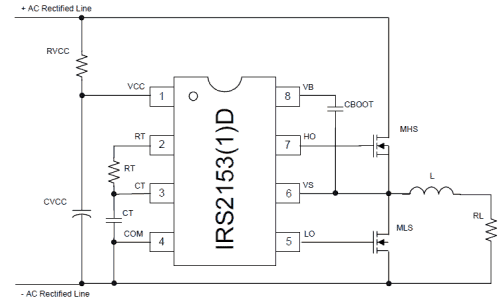
Understanding Pinouts of the Half-Bridge Driver IC IRS2153(1)D
The figure above shows the standard circuit configuration of the proposed half bridge IC. The pinout functions may be understood as follows:
Pin#1 is the Vcc of the IC and is internally clamped to 15.4V for safeguarding the IC from high supply voltages.
The RC network made from RVCC and CVCC has two important functions, the resistor hleps to control the current to the internal zener while the capacitor provides a start up delay to the chip so that the outputs are able to initiate with zero logic until the built-in oscillator has begun oscillating.
The resistor Rt and Ct across pin#2,3,4 is the external RC network which determine the oscillator frequency (duty cycle being fixed to 50% internally).
The following formula can be used for determining the oscillator frequency:
f = 1/1.453× Rt x Ct
Pin#4 is the ground terminal of the IC.
Pin#7 and pin#5 are the High and Low side outputs of the IC, meaning pin#7 drives the mosfet which is connected with the supply voltage while pin#5 is responsible for driving the mosfet connected with the ground rail.
Pin#8 is terminated with a Cboot capacitor which ensures that the HO and LO never conduct together and also steps-up the required bootstrapped voltage for the HO pinout of the IC.
Application Note:
The main application of this IC hovers around inverters and converter topologies.
One standard inverter application design can be seen in the below given diagram:
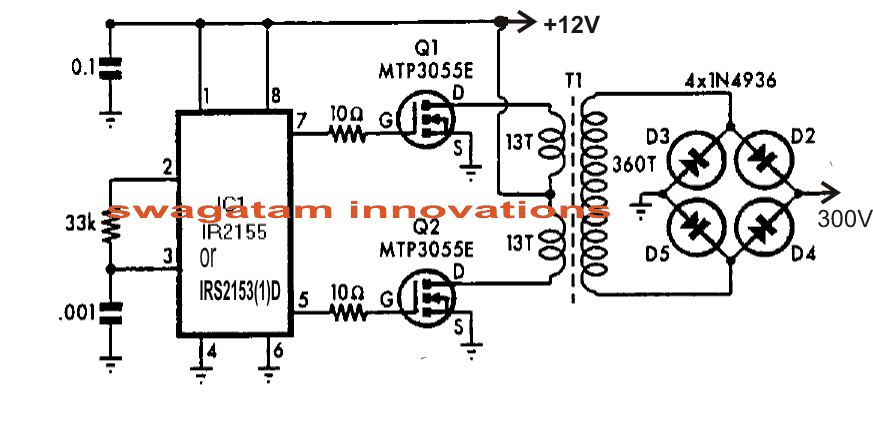
The simple inverter design shown above using the IC IRS2153 can be used for driving mains CFL lamps from 12V supplies.
Here the Cboot feature is eliminated because the configuration is an ordinary center tap type inverter which does not call for boot-strapped supply due to the absence of high side mosfet network here.
The transformer may be wound over any standard 27mm E-core type ferrite assembly, as shown below.
For the complete datasheet you may refer to the following post:
irf.com/product-info/datasheets/data/irs2153d.pdf

Comments
Could you use this device to drive a vibration bowl feeder.
Dear Raj. I can't find irs2153 in here, but i have found ir2153. May i subtitude with this? Thanks
Dear sir swagatam
Thanks for your quick response.
I checked the ic ir2153 pins with LEDs and they shows flicker in change of frequency with respective 5k rotary pot.
But on connecting to igbts the ic getting hot and ic get dead.
Any solution for its
Thanks 🙂
Dear Raj,
an LED testing will not show anything, you should test using a frequency meter, the frequency should be above in kHz over the output pins…..may be between 20 kHz to 100kHz depending on the position of the preset 4k7.
you can confirm by keeping the IGBT gates disconnected from these points.
but anyway the IGBTs will never load IC outputs since the IGBTs have a high gate resistance…so the IC should not get hot under any circumstances, something could be wrong either with the IC or the connections somewhere.
Dear swagatham sir
Myself raj doing ms on organic chemistry. But i have lot of interest on electronics and high voltage equipments. Recently I'm working on solid state Tesla coil buy using ur2153 ic and igbt from this schematic
sstc4.png – https://docs.google.com/file/d/0B8xT7Q4vaK-bYVRTTnRseHZqb1U/edit?usp=docslist_api
I did the same circuit as shown in the schematic but its not working
Any troubleshoot tips will be greatly helpful
Thanks again in advance
Dear Raj, check and confirm the following basic issues first, check whether the pin7 and pin5 are generating the frequencies correctly using a frequency meter.
Confirm the above by varying the 4k7 pot, the frequency should also accordingly change at these points in response to the 4k7 adjustments.
Next connect some kind of load at the output and measure current across each IGBT between their collectors and the positive line….optimize and make it to maximum by gradually adjusting the 4k7 preset.
Beware that the circuit is not isolated from AC mains, and can give a lethal shock if not taken appropriate precautions.
Hello sir,
while browsing the datasheet of ir2153 ic, i noticed its specs says has a 50% duty cycle.
now my question is that,
with whatever values of r and c i use, and assuming a certain frequency at the output,
would the duty cycle be stable at 50% ?
i am building an emergency tube light circuit having;
1. a 2 feet tube 20w
2. primary center tapped ferrite transformer
3. inverter config. will be a push-pull type, i will be using the 2153 ic.
4. power source is 12v sla batt.
Currently, i am trying this circuit.
Please help.
Hello Sherwin,
whatever may be the values of R and C, the duty cycle will be 50% only the frequency will change.
you can try the design for the mentioned purpose, if correctly implemented it should work.
Hello sir, i am planning to build a switching power supply. There are some few questions:
1. what is the frequency rate at which smps'es transformers run.
2. at which waveform they are operated.
One thing is that i built my own ferrite transformer for my smps, made it on a ferrite rod from an old radio.
I wish to use the above driver shown, but at what frequency i must set the circuit to operate the trafo??.
which diode should i use for trafo. output rectification?
input to circuit=12v from sla battery, output from circuit 3v 0.7-1amp are my specification.
Thanks and please help me.
Hello Sherwin, any frequency between 20kHz and 100Khz can be suitably used with ferrite transformers.
waveform is not critical, ordinary square/rectangle pulses will do
for the diodes you can BA159
if you are trying to make a simple buck converter you could make use of IC555 easily, special driver ICs as above may not be required.
hello dear,
i am to build a switch mode power supply and thanks for getting me to this page in the blog.
My specifications are:
1. Input to smps will be 12v
2. Output will be 3v
Presently, IC IR2153 is new to me and i am still learning about it. And one thing, what is the function of PC817 optoisolator ic, in any smps which role does it play?
Thanks and please help.
hello sherwin, look for IC 555 buck converter circuit and configure it appropriately as per the mentioned specs.
the opto is for feeding the output voltage to the circuit's voltage sensor stage in an isolated manner in order to monitor this feedback data and cut off in case the output tends to go beyond the set safe limit
Will the frequency depends upon capacitor tank of induction heater if i use ir2153 ic?
capacitor across the coil will not be required if a IR2153 driver is used
Call you please tell how to connect this IC in Induction heater to prevent mosfets burn
homemadecircuitsandschematics.blogspot.de/2013/10/simple-induction-heater-circuit-hot.html
Please Tell The Value of RT & CT to get 200KHz
you can try the second circuit configuration shown in the above article.
Ignore the secondary winding and the ferrite core, replace the center tap primary with the coil as explained in the induction heater article.
200khz may be set by adjusting the resistor or the capacitor and verifying with a frequency meter
can i use IR 2151 or any other Self-Oscillating Half-Bridge drive for induction heater?
yes, it can be tried, but the frequency will need to be adjusted until the optimal resonance frequency is achieved.
1. Is it tested by You to give a sine wave?
2. How will d ferrite TRF b connected
it's not a sine wave, it's a square wave design.
the trafo will need to be soldered on the PCB for the connections.