A wireless microphone is a portable electronic microphone which allows the user to transmit its voice to an amplifier without any wire connection, hence the name wireless microphone.
Making a wireless mic at home can be real fun, here I have explained one such simple project which can be used for recording and paying back your voice wirelessly.
Introduction
Cordless microphone and amplifier units are generally used during public address programs, stage entertainment programs or in all forms of occasions where voice signals are required to be amplified so as to make them audible over a wider area and distance.
However since microphones are normally held by the hand while speaking, the unit needs to be perfectly hassle free so that the individual holding it is able to move about the premise freely.
In this article I have explained how to construct a simple wireless microphone circuit and use exactly for the above intended purpose.
What is a Microphone
A microphone is a device which is able to convert voice or sound vibrations in the air into electrical pulses. They are generally used for public address purposes and entertainment programs.
Here I have explained a very simple way of making an FM wireless microphone circuit that requires no wires for the specified operation
Older types of mics carried a wire or an electrical cord from the mic up to the amplifier, making things very cumbersome and inconvenient for the user.
The cord used to dangerously dangle about the legs of the user making him vulnerable to entanglement and even stumbling because of the mess.
This led to the invention of much sophisticated wireless types of mics which became much comfortable to handle and use on any platform, moreover the distance of the user from the amplifier also was no longer an issue now.
However the invention could take place only after the invention and improvements in the FM broadcast technology, because the wireless mic actually incorporated a small FM transmitter which sent the voice signals in the form of FM waves to the FM receiver before it could get amplified in to the loudspeakers.
These wireless mics are still being used effectively for the intended applications and have become quite indispensable with the specific users.
Though the device may look quite sophisticated with its operations, but did you know it is actually very easy to construct at home and therefore can be made by any electronic enthusiast?
It is definitely one of the best fun electronic projects as it not only provides thorough amusement while making it but can be proudly used by the constructor for displaying the impressive wireless transmission capabilities of the built device.
Circuit Diagram
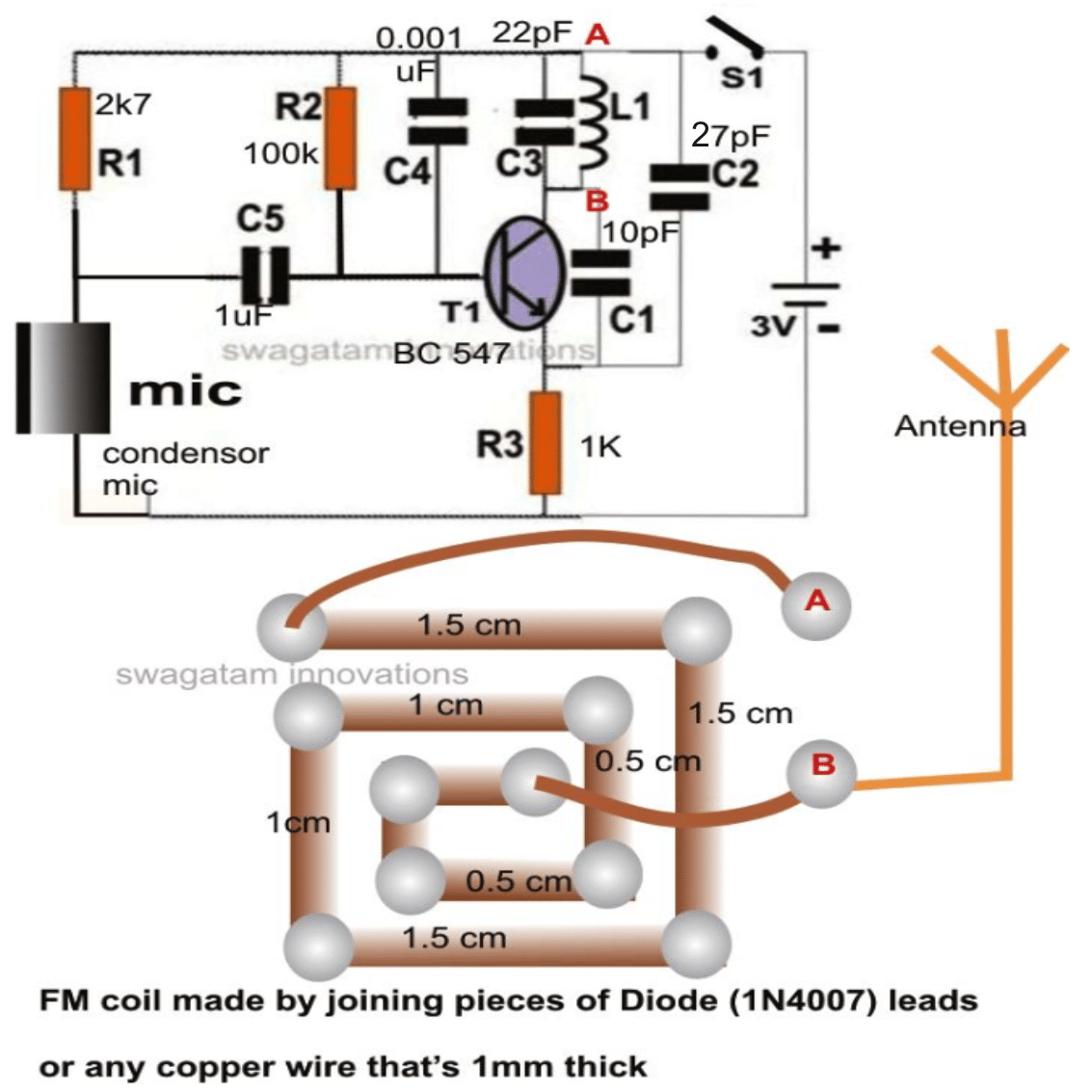
Parts List for the wireless microphone circuit
- Resistors are 1/4 watt 5% CFR
- 2.7 k = 1
- 100 k = 1
- 1 k = 1
- Capacitors are ceramic disc
- 1 µF = 1
- 0.001 µF = 1
- 22 pF = 1
- 10 pF = 1
- 27 pF = 1
- Transistor BC547 = 1
- MIC electret = 1
- 3 V Coil Cell = 1
How to Make this Wireless Microphone Circuit
Let's try to understand how to build a wireless FM microphone circuit.
The mic section actually consists of a mini FM transmitter which is so small that literally it can be accommodated in a space of less a square inch and if its made using SMD, it could well be made within an area of 1 square cm.
Actually the unit can be experimented in many different ways as the parameters involved are truly flexible.
The power consumption being negligible allows us to use button cells for the operations.
However pencil cells would be more preferable if the unit is intended to be used for long hours of speech transmission.
The main active part of the circuit is the general purpose transistor, while the other supporting passive parts are also very few making the item very compact as far as part count is concerned.
The circuit assembly strictly does not require a designed PCB, nope! And in fact is not recommended either.
The whole circuit can be fitted over a small piece of veroboard, or probably if you have a good hand with soldering, you would be able to stitch the parts together over a thin piece of plastic or rubber strip.
The figure shown alongside illustrates the details of the transmitter part, all that’s required for completing the wireless microphone section.
A plastic pipe or any similar enclosure may be used for housing the circuit along with the battery and the switch.
How the MIC Circuit Works
The transistor, the inductor and the relevant capacitors are mainly responsible for generating the FM carrier waves; the configuration quite resembles a Colpitts oscillator.
The capacitors C1, C2 and C3 mainly determine the oscillator frequency and can be altered for changing the reception positions over the FM receiver band.
The MIC converts the voice signals spoken close to it into electrical pulses.
These electrical pulses hit the base of the transistor, which now suddenly functions as an audio amplifier, amplifying the signals at its collector arm.
However since the tank configuration responsible for manufacturing the carrier waves is also included at the collector arm get influenced by these amplified voice signals.
The carrier waves now start getting modulated or rather ridden by the audio signals constituting the transmission of the audio in the air.
The transmitted waves can be received over any standard FM radio receiver, or if the unit is to be operated directly in association with a high power amplifier unit then probably a FM receiver module may have to be built with a headphone jack integrated for allowing an easy plug-in with the amplifier LINE IN socket.
The FM module are easily available ready-made in the market with presets for the necessary frequency adjustments.
These are quite small PCB assemblies having built-in presets and discrete outputs for volume control, audio, and antenna.
The only section that does not become a part of these assemblies is the amplifier which any way we don’t need as the amplification function is primarily associated with the PA system where the FM module needs to be fixed through the relevant LINE input sockets.
The FM module can be easily accommodated inside a small plastic square box with the embedded large jack protruding out of the box and also the antenna in the form of a neatly wrapped flexible piece of wire.
However for hobby purpose you may use your home FM radio for the receptions.
Testing and Setting up the Microphone Transmitter
Once the transmitter is built, it may be tested with the following few simple steps:
Connect a 3 volts supply to the circuit, preferably from two AAA pencil cells.
Keep a FM receiver somewhere around the transmitter at about 2 meters from it initially and start tuning the receiver until you find the “null” spot where the “hissing” from the radio suddenly becomes zero.
Now tap or speak loudly over the mic of the transmitter, which should be audible over the receiver clear and loud.
Now take the FM radio further away from the transmitter to about 10 meters and repeat the procedure by readjusting the tuning of the radio until the reception is crystal clear.
The testing of the wireless mic is done and it’s ready to be used.
House the e entire assembly inside a suitable enclosure as described in the above section and you are all ready with an efficient cordless microphone…….Well,.. now nobody can stop you from becoming a home-brewed karaoke rock star.

Comments
Earlier i have a readymade FM mic that has almost same circuit. That uses BF494 instead of 547.
yes, the above circuit was also taken from a readymade commercial design.
Hi
I am a doctor from Tamil Nadu. I am trying to make a small circuit to transmit a mic input to a bluetooth headphones. I want to attach the mic with amplifier to a traditional stethoscope head unit so that, i can hear the heart and lung sounds with a bluetooth headset. This is especially important in these Covid times, where the traditional stethoscope makes you lean close to the patient’s face making the doctor at increased risk of exposure.
hi, for this you will need the following two items:
Once the two are joined, then hopefully it may help you to achieve the requirement
hi, so the fm coil need to be make to a square and attach it to antenna?
what is the length of antenna needed
Hi, yes that’s right, the square shape is more convenient to build, the antenna could be a 6 inches long flexible piece of wire
Greetings sir. Can i ask Whats the output frequency from this transmitter?
Ben, it is the same what we have in normal FM radio bands
Hey bro..wat can i change in my mic transimeter to accept all fm recievers?i losted my compatible reciever of the mic,so wat i have is different
Hi Brian, if your FM MIC is able to work with one FM radio then it means it will be able to work with all FM radios, because the FM band range is the same for all FM radios, it cannot be different for different FM radios
Is it ok to use 1mm diameter enamelled copper wire as the coil?
will do…
i ve mini fm wirless microphone i wanna convert it to wired to use it to connect to pc
it can be a little complex, better to buy a MIC with a 3.5mm jack or an USB
Sir was it possible to modify this to transmit fm radio wireless to distance around 2kilo meter if yes then how
Thank you
Manjunath, a two km design will require a lot more stages and complex set up, you can try the following circuit instead:
https://www.homemade-circuits.com/2013/05/long-range-transmitter-circuit-2-to-5.html
sir can i connect my mobile to play music in FM ( music that plays in mobile should transmitted to fm reciving module)
that mean can i use my mobile as an fm transmitter
Manjunath, yes definitely you can do that! you can use your cellphone's headphone music output with the the above explained transmitter for listening to it on an FM radio wirelessly.
I'm not able to get a 1uF ceramic capacitor! Pls help me out…
1uF value is not critical, ceramic is not critical, you can use any capacitor between 1uF and 100uF
Nice one… But i would like the mic to transmit the data over wifi to a receptor…probably a phone so the phone plays it.. Is there a way to do that or will i have to build a mobile application that can convert the sent data from the mic to the mobile phone?
sorry, that looks difficult, I have no idea about it
sir please tell me step by step that which thing will be require to make this device. please tell me sure name of every part which i can buy from market.
Bilal, all the resistors are 1/4 watt 5%, and all the capacitors are disc ceramic type, except which is 1uF/16V non-polar electrolytic, the MIC is an "electret MIC"
Can I power it w/ 9v battery? tnx
yes you can but it'll be unnecessary waste of energy…
is the switch must in the circuit ?
you can use a small microswitch, push-to-On type.
2n2222 will also work
thanks for replying me. Could you tell me what type of switch I can use ?
and is it ok to use 2N2222A transistor ?
yes it is….
CAN I USE MOBILE MIC IN THIS CIRCUIT
not sure about it
In your Simple Wireless Microphone Circuit the signal is catch by mobile radio .
yes it will but within 10 meter range
PLEASE HELP: I have a stalker doing this to me in my houses and in my cars. Please help me to know where to look to find it. I think it may be somewhere around my AC. Would that be a good place to start? What all would I look for?
you can use the following circuit for sniffing out the exact location of the transmitter bug:
https://www.homemade-circuits.com/2012/01/how-to-make-ghost-detector-circuit.html
switch OFF mains power before you carry out the sniffing procedure with the assembled circuit so that mains disturbance does not hinder the procedures
Someone is doing this to me in my house and cars. Where is the best places to look to find it? I think it may be connected to my AC is that a good place to start?
We cant make exact square inductor. Is it effect our transmission
slight changes in the wire formation will not affect the results
Sir please tell me how to design inductor in detail. If small unwanted bend occurs is it effect our transmission ??
hi this is aswin. how to convert this circuit transmit the signal above 500meatter. can you help me. aswindcn@gmail.com. kindly help me guys.
can you replace the components so that the frequency will broadcast on the lowest MHz of an fm radio. i think the lowest frequency is 85MHz or 87MHz?
you can do it by slightly tweaking L1 or C2. Either reduce the value of C2 or increase one turn on L1, or reduce the diameter of L1, or squeeze/press L1 sightly with your fingers to tighten the gaps between the turns.
do you mean that the coil is not cylindrical but instead a square like in the picture?
that's correct