In this article I have explained how to make an LED dimmer circuit for enabling a dimming facility to any mains operated LEDs bulb.
Update: [Using Capacitors, it Works]
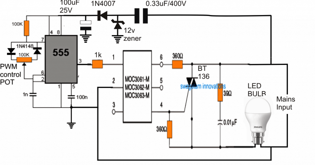
If you think PWM dimming control might not work for commercial LED bulbs, then the best method is to use series capacitors, which might just do the trick.
Using selectable high voltage capacitor series capacitors can be used for dimming control of all ready made commercial LED bulbs without any problems, as shown below.

Understanding The Basic Idea
Let us first understand that this circuit is working only because we are putting different capacitors in series with the LED bulb supply line.
So we can say that we are using the capacitors as the main current controller. Now you select one capacitor at a time through the rotary switch, and that capacitor decides how much current will flow to the LED bulb.
How The Capacitors Control The Current
We know that a capacitor does not behave like a resistor. Since a resistor drops power by heat, a capacitor does not do that.
A capacitor creates a reactive impedance that is called Xc. So this Xc will limit the AC current. The formula for this is written as:
Xc = 1 / (2 × π × f × C)
Now we can see that when C becomes smaller, then Xc becomes bigger and current becomes less.
When C becomes larger, then Xc becomes smaller and current becomes more. So you can say that small capacitor gives dim light and large capacitor gives bright light.
How The Rotary Switch Makes The Steps
The rotary switch is simply selecting only one capacitor at a time. Let us say you rotate to the 0.047uF position, then you get very low current and very dim LED.
When you rotate to 0.1uF then brightness increases slightly. When you rotate to 0.5uF then LED becomes medium bright.
When you rotate to 1uF then LED becomes almost fully bright. So the rotary switch is like a step-by-step brightness selector.
How The LED Bulb Reacts Internally
Inside the LED bulb there is a small driver circuit. This driver wants to maintain some constant power or constant current inside the LEDs.
So when you limit the input current with the capacitor, the driver automatically reduces its output to the LED string.
That is why brightness reduces smoothly. Since the internal driver is stabilizing everything, then you normally do not get flickering also.
Why There Is No Heat Produced
Let us note that there is almost no heat in the capacitors because they are reactive parts. So they do not burn any power like resistors. That is why this dimmer becomes very efficient for LED bulbs.
Why Only High Voltage Capacitors Are Used
We must use 400V rated polyester or polypropylene capacitors. We must do this because the capacitors have to handle the full AC voltage which has a peak of around 310V.
So these capacitors must tolerate high stress. You should not use low voltage parts here, since then they will fail very soon.
Brightness Steps You Usually Get
With 0.047uF you get very dim night lamp kind of light.
With 0.1uF you get dim light.
With 0.5uF you get medium brightness.
With 1uF you get almost full brightness.
The exact brightness can change from one LED bulb model to another, but the general idea stays same.
Important Things To Know
Now let us discuss some important points slowly.
When the LED bulb has isolated SMPS, active PFC, or high level constant-current driver, then sometimes the bulb may not dim smoothly at very low current.
The bulb can even shut off. So this method works best for simple non-isolated driver bulbs or basic capacitor-dropper type bulbs.
Since the entire circuit is connected directly with main AC, then there is no isolation. So every part of the circuit remains at high voltage potential, and you must handle with care.
Since capacitive dimming cannot reduce the voltage to zero, then you cannot get completely OFF brightness unless you add one OFF position in the rotary switch.
Summary
So in this method we simply put different capacitors in series with LED supply. That capacitor limits the AC current according to Xc.
The LED driver receives less current and then it reduces its output power and you get dimming. The rotary switch selects the amount of current and that gives you different brightness levels. This becomes a very simple and efficient dimmer because it uses no heat and no TRIAC.
Using PWM Dimming Control is the Best?
We know that our ceiling fans and incandescent bulbs can be easily controlled using triac dimmer switches, and we are quite used to with dimmer switches in our homes installed for controlling such devices.
However with the advent of LED bulbs and tubes, incandescent bulbs are slowly making an exit, and our home bulb holders are getting replaced with LED bulbs.
LED bulbs come with a built in SMPS driver within their holder cabinet, and an SMPS circuit makes it difficult to operate or control through a triac dimmer switches, until and unless its suitably modified for the application.
Because, the SMPS driver inside LED bulbs and tubes strictly employ inductor or capacitive based circuits which are never recommended to be used through triac dimmers, since triac dimmers utilize phase chopping technology for the dimming purpose which unfortunately does not suit inductive/capacitive load control.
If used then the LED bulbs do not dim correctly rather show erratic dimming or brightening behavior, due to an incompatible reaction.
The best method and probably the technically correct approach is the PWM technology which can be effectively used for controlling or dimming LED bulbs or tubes. The figure shows the design may be implemented.
You may also like: Simple DC Lamp Dimmer Circuit
Problem in the above Method
A deeper inspection of the above concept shows that the concept might not work due to the presence of the internal filter capacitor in every LED bulb circuit, right after the bridge rectifier.
This filter capacitor will hold the charge and keep the LED bulb ON even during the OFF times of the PWMs, preventing the dimming effect.
This means that dimming an LED bulb through an external means can be impossible.
However, the dimming effect can be perhaps implemented by connecting the series LED section of the LED bulb with the IC 555 circuit, as indicated in the following diagram:
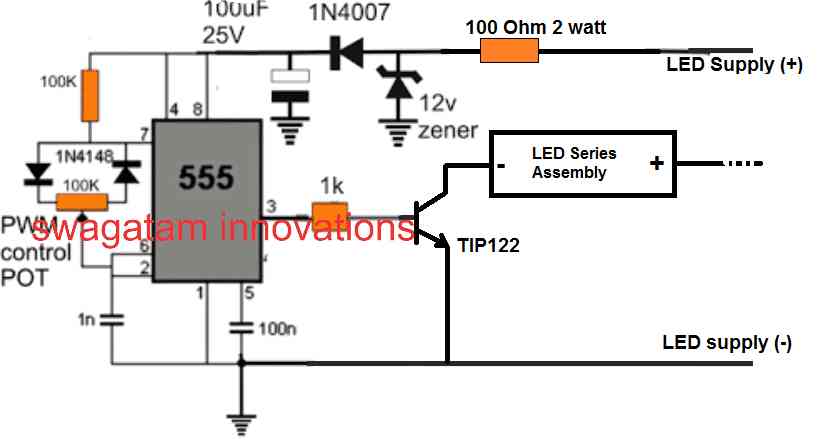
We know that an LED bulb circuit is nothing but a small AC to DC SMPS circuit, which employs a small ferrite transformer for stepping down the mains voltage to a lower LED DC voltage. The secondary side of the transformer produces the stepped down voltage which is rectified by a single diode and a large filter capacitor.
The rectified DC is then transferred to a series LED assembly for lighting it up.
We have to modify this LED section and connect it with the IC 555 PWM stage as shown above.
This can be implemented wiht the following steps:
- Open the LED bulb container.
- Cut the wire of the LED assembly which goes to the negative line of the DC supply.
- Connect this negative LED wire to the transistor collector of the 555 pwm circuit.
- Finally connect the 555 pwm circuit's positive/negative wires with the LED DC supply, coming from the ferrite transformer secondary.
- This also means that the 555 IC circuit does not need an external DC, and it can be derived from DC supply from the smps, meant for driving the LEDs.
- Finally, connect the LED smps input to AC mains and check the dimming effect by varying the IC 555 pwm pot.
- Remember the smps circuit primary side is not isolated from mains and therefore extremely dangerous to touch in switched ON condition.


Questions & Answers
I’ve been looking for a simple method to dim LED bulbs that doesn’t require PWM, and yours might be the answer. However, our domestic electricity is 120vac so I would assume the specs on the capacitors will be different. Could you please provide what those numbers would be?
With thanks!
Yes, I tested the first design with a 0.1uF/400V capacitor and found the light to be significantly dim. But I did not check with other vales, so i am not sure how other values will create the difference in its illumination…
For 120V AC you can use the same setup, or maybe use capacitor rated at 250V, which will be cheaper…
Hi Sir, i want to try zero crossing method for my Halogen tube stovetop, can i use this 555 Bulb Dimmer circuit or is there any other zero crossing driven circuit with pwm generator?
Triac is BTB16-800 for two 500 watt Halogen tubes.
Hi Tym,
A triac based AC circuit might not work well with a DC PWM.
Instead you can go for an AC dimmer circuit as explained in the following article:
https://www.homemade-circuits.com/how-to-make-simplest-triac-flasher/
Sir first thank you for all the useful circuits you have been posting all these years. My question, if we use a dimmable LED is this circuit going to work, or we face the same condition with the presence of a filter capacitor? Thank you in advance.
Thank you Alfa,
I am not sure how the dimmable LEDs are designed to work, whether they have internal SMPS, do they work with 220V AC? So I am not sure whether the first circuit from the above article can be used with these LEDs or not.
Finally, I found the time to try connecting dimmable LED lamps in this circuit. It didn’t work.
I tested one Phillips 20W LED bulb with a 0.1uF/400V series capacitor and it became significantly dim. The light was equivalent to a 3 watt lamp…
Hi Swagatam;
When considering the dimmer circuit I am not sure which one is changing or being limited, voltage or current or both of them by the control pot.
For instant; when we use that circuit with the load as bulb 220 Volt AC. I think sensitivity depends to the circuit parts specs and let’s say the voltage is being changing as minimum 70 Volts and Maximum 210 Volts. But if we need a fixed / constant voltage about 120 Volts in the circuit, It is possible to gain that thru another simple circuit or only alternative is dimmer circuit for the purpose? Regards
Hi Suat, an AC light dimmer controls the output voltage by chopping the AC mains cycle into smaller sections. If you need fixed voltages from the dimmer then you can replace the pot with a 5 step rotary switch having 5 calculated resistors for 5 different fixed voltages. An example is shown in the last diagram from this article:
Light Dimmer and Ceiling fan Regulator Circuit
Hi Swagatam;
Please do not consider my previous message since I am confused for a while I will advise the result later- Thanks
OK no problem…
There were 2 pieces of BT136 on the PCB and one was switch and other was dimmer so I was confused and thought as if the dimmer were switch. So no problem and that is normal the bulb is on at the dimmer circuit. Thanks anyway.
OK got it, no problem.
Hi Swagatam;
I am sure above circuits are better however there are simple dimmer circuits too. Parts are Bt136, 39K, 104 or 105 C, DB3, pot 500K or equivalent parts. I have the one like that although there is no short contacts among the pins of BT136 Bulb always lights even no Gate voltage. I need your opinion. Thanks and regards
Hi Suat, The LED bulb has a bridge rectifier inside which makes it a DC load for the triac, and since a triac can latch up with a DC load, therefore the triac may be conducting even without a gate voltage since it has latched.
Hi Swagatam,
I’m wondering here if I remove the capacitor from a led bulb, which circuit above will REALLY work?
Tks,
Marcelo
Hi Marcelo, if the LED itself works without the capacitor then I am sure the dimming can be implemented using the above concepts.
Hi Swagatam,
Even the 1st circuit using the opto-coupler is all fine? All we need is just to remove the blessed capacitor and then it will work?
Tks,
Marcelo
Yes the first should work if there’s no filter capacitor installed inside the LED bulb. This is as per my assumption, but will need to be verified practically.
I think the problem by removing this filter capacitor is surely the DC circuit will become unstable, as no filtering will be present anymore.
You may be true, but it will need to be confirmed practically.
Thanks for your attention, Swagatam. But I’m wondering here if along these almost 6 years that this thread is open nobody managed to test successfully any of your concepts yet?
Yes because the concepts are not easy to implement, and are not confirmed.
Does a triac only work with resistive loads? Or if they have a reactance (capacitive or inductive) it must be negligible with respect to resistance.
But in this case, the led bulb has an electronic circuit internally and therefore it is not even a line load. If it works, why does it?
Triacs can work with resistive and inductive loads both. But yes, an LED bulb might not work with a triac, the first circuit needs to be revised and changed.
I think 555 as PWM doesn’t make sense, the circuit only serves to activate or deactivate the load like a relay. To control the brightness (assuming it works with the led lamp), by means of the MOC3061-M circuit it is possible to detect the zero crossing of the AC voltage and based on that, a time is waited to activate the TRIAC (firing angle) , nothing to do with a PWM
The PWM definitely makes sense, it decides how many milliseconds the triac needs to remain switched ON and for how many milliseconds it needs to remain switched OFF, during each 50 Hz cycle. It is called zero voltage switching or time proportional triac drive.
It keeps the load switched ON for an average length of time which causes the brightness to change depending upon the PWM duty cycle.
But due to the internal filter capacitor the ON/OFf duty cycle can be ineffective, since the charge inside the capacitor will compensate the switch OFF periods and keep the LED ON with a constant brightness.
But when you activate a TRIAC, it remains active (conducting) until the voltage drops to zero. Therefore, with the first positive edge of the PWM, the triac will activate and thus the PWM signal returns to zero, it will not turn off.
Only when the AC voltage signal drops to zero will it turn off.
The TRIAC is not like a transistor that turns on or off depending on the voltage present at its base.
The TRIAC and similar devices are activated with a pulse on their gate and the only way to turn them off is for the voltage at their terminals to go to zero volts or to apply a reverse voltage to them.
Yes that’s right, triacs get latched until the next zero crossing arrives, and this feature can be used to break the triac switching.
In a 50 Hz AC cycle, the zero crossing arrives 100 times….so that triac can be switched ON/OFF anywhere during these 100 zero crossings.
If the PWM is adjusted for 50 ms ON and 100 mS OFF, then after 50 ms the triac will OFF for 100 ms and then ON again for 50 ms, and this will go ON….causing a proportionately reduced average ON time. In this way many other PWM duty cycles can be used for controlling the triac’s average output ON time
Sir I can not find an SFH619A opto-coupler. Can MOC3021 be used instead?
Naamal, the opto in the second concept should be a LED/transistor based opto, whereas MOC is a LED/triac based opto which might not be suitable for this application
Thank you so much for answering me sir
You are welcome Namaal,
Hello,
Do you mean we can dim a unmodified AC power LED Bulb with your DC BJT based circuitry ?
Thanks, Denis
Without removing the internal filter capacitor, external PWM control may not be possible!!
hello, nice work on this circuitry. Can it be implemented on a no-nuetral connection? like in the light switch with only the live wire..?
Hi, thank you, no it cannot be implemented without a neutral connection for the circuit
Could I drive the MOC3063 with the PWM output of a WS2811?
I have not yet studied WS2811, so can’t advise on this…
I have encountered 120Vac LED’s that incorporate a small transformer and so will not work from DC. A simple solution is to remove bulb from between the transistor and the DC side of the bridge rectifier, and connect it in series with one of the AC legs of the bridge rectifier. This will allow the transistor to pwm on the DC side, controlling the AC voltage. Should work for either type of LED.
LED bulbs can actually work with DC since it incorporates a bridge rectifier and a filter capacitor, at the very start of the circuit, just like an SMPS. So basically they work with DC only. However, the external PWM will not work, because during the OFF periods of the PWM cycles the internal filter capacitor will keep the LED circuit switched ON and thus the PWM will not be effective.
So if this filter capacitor is removed then the bulb could be dimmed externally through a PWM.
Switching the circuit internally can be a little complex, and moreover all LED bulbs do not incorporate a transistor.
I have retrofit LED’s in my plant, how can we implant dimmer circuits in them to save energy.
Please provide the full specification of the LED units.
Actually retrofit in sense first they were CFL rods two pin earlier now same has been replaced with LED rods. As I have learnt from the thread that these LEDs have a capacitor inside which prevents this circuit to work. What could be the alternative. If you can share your whatsapp number I will share photographs.
The capacitor will need to be removed if a PWM based dimmer is used. PWM is the only method which can be used for dimming mains LED bulbs, other methods might not work due to the presence of the internal circuit.
Sir we have Philips led rods in which
1. Rectifier MB10f
2. LED driver BP2338
3. Inductor
Kindly share personal email address so that I can share you pictures also. If any solution we can prepare.
Gagandeep 9779732634
As per your 555 timer circuit kindly suggest me the values of components (resistor- capacitors-Diode) along with wattage. I want to design this pcb for trial on 18 watt LED.
You can use the same circuit which is explained in this article:
https://www.homemade-circuits.com/making-adjustable-electromagnet-circuit/
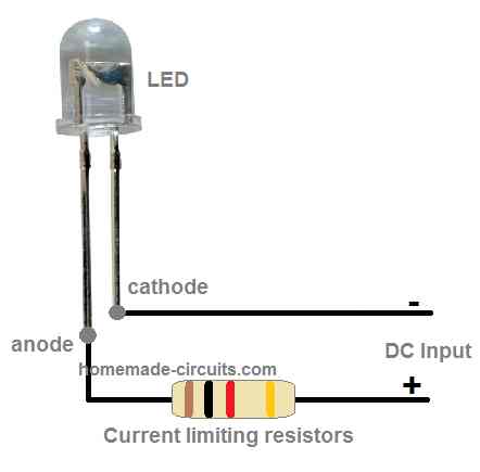
Please remove the electromagnet/diode, and connect the LED cathode side with the transistor collector. The anode side of the LED will go to the positive line. The negative of the 555 circuit will be common with the negative of the LED controller circuit.
Te supply to the IC 555 should be not exceed 15 V DC
Hi, Thanks for the update kindly guide me what should be the values of components for 18 watt led.
Hi, I don’t have enough information about this IC, so I can’t suggest much about the components.
Yes same circuit
OK, then please check the voltage across the LEDs so that we know the DC available from rthe circuit which can be also used to power a separate 555 pwm circuit for dimming the LEDs. The BP2338 IC cannot be modified for dimming. We will have to add a separate IC 555 stage for the dimming.
Hi Gagandeep, are you referring to this circuit:
Hi Swagatam,
Ref: LED Dimmer – Simplified Design
You mention the circuit is not isolated from mains. Any fix for this yet?
Also mentioned in thread is to change 1k series resistor at optocoupler to 10k-22k. There are 2, 1 in from 555 IC and 1 out to BJT. Change both?
Finally, what 12v Zener rating.
Thanks,
Marc
I caught the comment about removing the internal cap from the LED from another thread but this kind of “shoots the idea in the foot” for a dummy using off-the-shelf bulbs for this. Works for you and me but a novice isn’t going to understand this work around. Interesting project though. Will try it for fun. Any 12v Zener will work?
Thanks,
Marc
The 12V zener can be a 1 watt 12 V zener diode.
Hi Marc, it is the right side 1K that needs to be replaced with a 22k. ou can isolate the IC 555 side by powering it from a separate AC to DC adapter.
However, there’s one issue with the design, unless the internal filter capacitor of the LED is removed, the dimming effect will not work
Hi swag,
want to replace an existing impulse relay with a dimmer device for my led lights installed in the ceiling, an impulse switch is installed to send power impulse to relay ? i am not very technical in electrical systems so my knowledge is very limited. please suggest can i keep my impulse switch and change the relay to make lights dimmabale.? can you also suggest any device?
Many Thanks.
Hi Zahid, you can keep the impulse relay as it is and use a dimmer in between the relay output and the LED.
Many thanks Swaq, will try that.
My pleasure!
Can we remove this circuit rectifier and supply 170 Volt DC current? Can the circuit work?
yes that’s possible. Actually even with an AC the external bridge is not required because the bulb already has a bridge internally.
Buen trabajo! Dispones de algún canal en Youtube donde has realizado el circuito?
Hi thanks, no I do not have a video for this project yet, however there’s one problem in the above designs. The internal filter capacitor of the LED bulb must be removed otherwise the above concepts will not work
Ok. Thank you very much 😉
Hi, I am not an advanced technician and i need this circuit for a project, so please i would like to know the caracteristics of the Zener and the optocoupler, because as you said “any optocoupler” and the zener reference is missing, i searched the devices datasheet and found that the optocoupler has a maximun voltage of 80V and the Zener only shows Vz, Iz and Pz. The thing here is that i am not sure of connecting the circuit to 120V AC main.
i searched the 1N4742A zener and MOC8050 optocoupler.
Please could you explain better the behavior of the voltages for over the circuit?
Thanks in advance.
Hi, yes the optocoupler needs to be a high voltage opto, I have changed the explanation and added the required number for the optocoupler IC. Also the series resistor with the opto collector is mistakenly shown as 1 K, please use a higher value in the order of 10K to 22K.
The design is not tested, but the concept is perfect according to me and therefore it should work as intended after some minor tweaking, …and connecting to with 120V should be perfectly safe for the circuit, except to a human touch. Since the circuit is not isolated from mains can be fatal to a human touch without proper precautions.
Hi Swagatam,
Can I use BTA41 in this circuit?
Regards,
Ender
Hi Ender, the last diagram is the recommended one, and you can use a BTA41 in it
Hi Swagatam,
Thanks for your info. I have some clarifications please let me know.
1. The LED bulb I am using is rated for AC 220V. If I supply 220V DC does this work? as it may have some circuit to step down AC to DC as needed. I can give a try, let me know if you have circuit for AC 220V to 220V DC conversion.
2. W.r.t your design the changes I have made is: Instead of 555 timer which generates pulse train I am using Arduino to generate the Pulse with required freq and duty cycle. So logically my circuit should work as yours.
Hi Vairaj, LED bulbs normally use an SMPS for powering the lamp, and since SMPS involve electronic circuitry they have to work with a DC input, so ultimately the mains AC is first converted to DC and then fed to the SMPS.
In my design I have used a triac and an optocoupler which might not work correctly for this application, your idea looks more appropriate.
Hi Swagatam,
I did check the PWM signal, it is varying and also when connected 5mm LED there is variation in brightness. So there is no issues with PWM signal generation w.r.t freq and duty cycle.
When tested with AC 230V LED there is no significant difference in brightness as said earlier.
The reason could be:
1. As the frequency increases the PWM pulse period decreases. If the frequency is above 5Khz and if the PWM duty cycle is lower( ex: <70) then the IGBT will get chance to turn on for very short time in each AC cycle. As a result the LED will not turn ON. If the PWM duty cycle is higher ( 100 ~255) then LED will turn ON but the brightness variation is not observed. The reason could be, the PWM pulse period compared to AC signal is very LOW so the difference in "ON " time for different PWM values becomes insignificant.
2. At lower PWM frequency (Ex: < 1KHZ) the PWM pulse period will be higher. In this case changing PWM values will result into brightness variation. But lower frequency causes flickering.
Let me know your views. What was your test setup and did you notice the above said issues.
Vadiraj, OK that means you are using the PWM with an IGBT and not the design which I suggested in the above diagrams, actually it looks to be a very sensible idea, because LED bulbs do not require an AC anyway, so no need of using triacs.
Therefore according to me involving AC is simply not required…convert the AC to DC using a bridge rectifier, then feed this to the Led via the IGBT. Once this is done, probably all the remaining issues will be automatically taken care of and you will find the LED dimming smoothly…try this and let us know.
Hi Swagatam,
Thanks for the suggestion. As you said above 5Khz PWM frequency flickering did not happen.
But I do not see any change in LED intensity. What I observed is, for lower duty cycle bulb, say PWM value below 50, bulb doesn’t turn ON. Then above PWM 50 till 255 the LED intensity is almost same. No visible difference in light intensity.
When I use only Triac dimmer, the one used for dimming Incandescent, I observe dimming happening as expected. Please let me know any suggestions.
Hi Vadiraj, I am glad you could solve the flickering issue, however the PWM issue will need to be solved through an oscilloscope.
Because if the PWM is varying correctly then the LEd ust also respond and vary its intensity accordingly. Therefore you may have to confirm this through an oscilloscope.
Alternatively you can simply connect a 5mm LED across the PWM output through a 1K resistor and check whether its responding to the PWM variations or not. The same can be done using a DC voltmeter,the voltage must show s gradual change in response to the PWM adjustment.
Hi Vadiraj, since I reply the comments through my website’s dashboard I sometimes fail to understand the reference of the comment…sorry about that…
are you referring to the first circuit in the above article?…if you are then I am afraid the assumed concept might not be entirely correct, that’s the reason I had to update the warning message at the end of the post.
Hi Swagatam,
I tried to implement AC LED dimmer using Arduino. Instead of 555 timer I used Arduino PWM signal. But I found that LED bulb flickers. I tried PWM between 0~255. Please let me know what could be the issue.
Hi Vadiraj, keep the frequency to a higher level, may be at 5kHz or more, this will prevent the LED from flickering.
Sir i need Dc led dimmer circuits…
I already use with 555ic Pwm method by using NPN…working good..When i see the led glowing in camera ..the led glows like sagging ..but in normal works good..when i see in camera its sagging sir….
I bought 1 emergency light with dimmer control…same i see in camera its not sagging….which type of circuit they are using….
Pls guide me sir
Is there any alternate circuit sir…
OK then you can use 1K, it will depend and need to be varied as per the current requirement of the load….
In base i use 10k resistor not working…but i use 1k resistor in base and 10k pot means working….
Is it correct sir or any idea
you already have the 10k from positive to base…so any other resistor is not required.
In the between of pot to negative voltage shall i connect 1 k resistor…
When the pot is fully rotate means the output will direct to transistor base …
Is needed resistor or no need sir
Kesava, you can simply use an emitter follower with pot for the purpose…as shown below:
https://www.homemade-circuits.com/2012/08/simplest-dc-cell-phone-charger-circuit.html
replace the 220 ohm with a 10K resistor, and replace the zener with a 10K pot
Dear sir how we can fade in fade out 220v ac lamp using ardiuno? Sir please help
Thanks for your help.
Hi Swagatam ,
I am a regular visitor of your page for more than 4 years. Thank you for your work with dedication and great interest, you have helped me a lot in refreshing my knowledge , improving and knowing new things.Great keep it up.
I have a 10W LED driver, I am using it for 10 X 1W LED.
My requirement is how could i drive two sets of 10 X 1W LED alternatively so when seen by us should be 20 lights glowing.
Thank you Jayaprakash,
you can use a transistor astable multivibrator circuit and connect the LEDs across the two arms of the circuit and oscillate the circuit at a rate that would almost make both the arms appear constant.
a transistorized astable circuit can be studied in this article:
https://www.homemade-circuits.com/2012/01/how-to-make-any-light-strobe-light.html
Yes sir. Triac is similar to scr. Once the gate is triggered scr lose it switching property until voltage reaches next half cycle. So I feel that generating high frequency pwm is useless because of this I am looking for a pwm in the range of 50hz.am I right sir??? Shall I use ic 555 to generate pwm for my requirement.
Vijay, PWM concept will not work for a triacs no matter what frequency is used,,,the phase chopping method as used in dimmer switches is only option of achieving some kind of PWM like control with a triac circuit.
Tnx for your response sir. Shall I operate 555ic to generate 50hz of duty cycle in astable mode of operation to generate pwm. Or do you have any other simple and most reliable idea than this.
thanks Vijay, triacs cannot be controlled through PWM, so it won't work….you can try the last updated deign in the article and let us know how it works.
Sir if ic 555 produces a frequency in the range of kHz. Weather it will affect the triac because triac should be triggered at every cycle when it reaches above the zero of ac to control the voltage..I think optocoupler zero crossing detector will take care of it am I right sir???
…or if the gate voltage from the MOC IC is facilitated to swing across a +/- voltages then the triac would respond and switch OFF/ON in accordance with the PWM during the AC cycles.
yes you are right, at every AC cycle the triac will get latched and the PWMs will have no effect….the idea needs to be reassessed
the 555 frequency will break the AC mains cycle into pieces, and the average RMS of this chopped AC cycle will determine the intensity level of the LED bulb
Vijay, yes the IC is positioned to make sure that the external triac and the load are operated at the most favorable conditions, however the concept could be applied even without a MOC IC according to me, since the most LED bulbs would be already having all the protection measures built-in.
What is the maximum pwm frequency from ic??? 555
should be set as per the triac's frequency handling specification