This project I will explain how we can control a relay remotely using a SIM card and a normal mobile phone, with help of Arduino and a GSM module. The relay can be turned ON or OFF by sending an SMS or by making a phone call to the SIM card placed inside the GSM module, so you do not need anything else.
Using GSM and SIM Card Only
The system works anywhere mobile network is available, so now internet is not required at all, just normal GSM coverage is enough.
A SIM card is inserted into the GSM module, and that module talks with Arduino using serial communication.
A relay module is connected to Arduino so it can control an external load. When the user sends an SMS command like ON or OFF, or when a phone call is made, then the GSM module passes that information to Arduino. Arduino reads the command and then switches the relay ON or OFF accordingly, simple flow.
Basic Components Required
The components required are Arduino UNO or Nano, GSM module like SIM800 or SIM900, 5V relay module preferably opto-isolated, SIM card with SMS and call facility, external power supply for GSM module, connecting wires, and an AC or DC load to control.
Powering the GSM Module
Now power supply part is very important here. GSM modules draw very high current spikes during network communication. Operating voltage is 4V to 4.2V, and peak current can go up to 2A, so do not power the GSM module from Arduino 5V pin, that will cause problems.
Use a buck converter or a dedicated GSM power supply, otherwise module will reset again and again.
Audio/Video Representation
Circuit Diagram
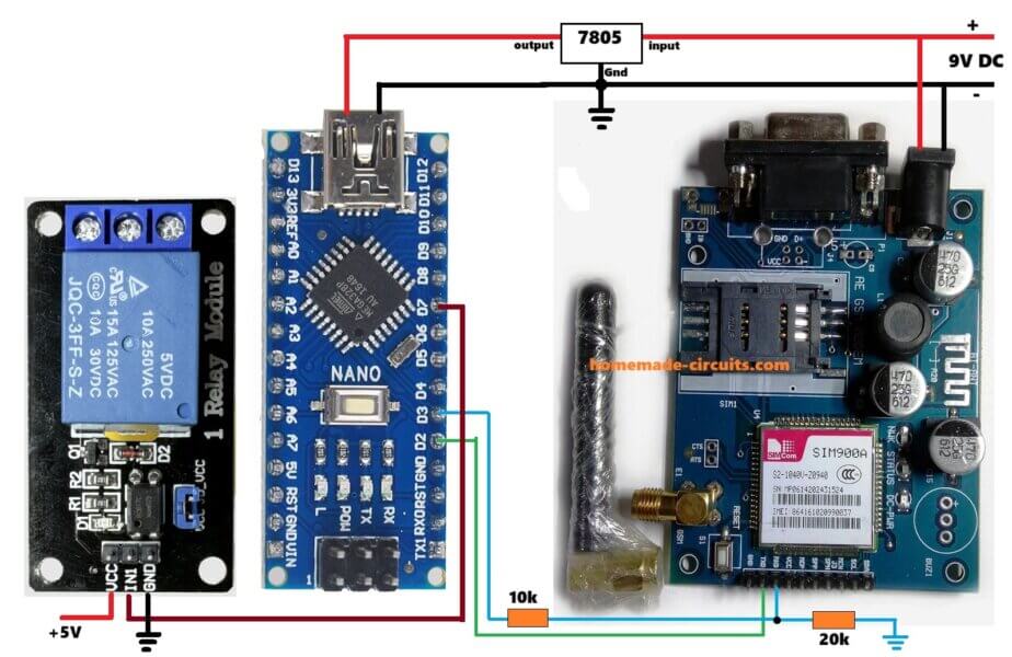
Arduino D2 → GSM TX
Arduino D3 → GSM RX (via 10K / 20K divider)
Arduino D7 → Relay IN
Arduino 5V → Relay VCC
Arduino GND → GSM GND + Relay GND
External 4V → GSM VCC
Circuit Connections
For circuit connections, GSM module is connected to Arduino like this. GSM TX goes to Arduino RX on D2 using SoftwareSerial. GSM RX goes to Arduino TX on D3, through a 10K–20K divider if required. GSM GND goes to Arduino GND, all grounds common.
Relay module connections are simple. Relay IN goes to Arduino D7. Relay VCC goes to Arduino 5V. Relay GND goes to Arduino GND.
For relay contact wiring, Relay COM goes to AC Phase. Relay NO goes to Load Phase. Neutral is connected directly to the load. Mains voltage is dangerous, so bro, if you are not sure, then please consult a qualified electrician before touching anything.
This project supports both control methods. One is SMS based control using ON or OFF commands. The other is call based control, where the relay toggles its state on every incoming call.
Arduino Code
#include <SoftwareSerial.h>

SoftwareSerial gsm(2, 3);   // RX, TX

#define RELAY 7

String incomingData = "";
bool relayState = false;

void setup() {
  pinMode(RELAY, OUTPUT);
  digitalWrite(RELAY, LOW);

  Serial.begin(9600);
  gsm.begin(9600);

  delay(3000);

  gsm.println("AT");
  delay(1000);

  gsm.println("AT+CMGF=1");     // SMS text mode
  delay(1000);

  gsm.println("AT+CLIP=1");     // Enable caller ID
  delay(1000);

  gsm.println("AT+CNMI=1,2,0,0,0"); // Instant SMS receive
  delay(1000);

  Serial.println("System Ready");
}

void loop() {

  if (gsm.available()) {
    char c = gsm.read();
    incomingData += c;

    // Check for SMS commands
    if (incomingData.indexOf("ON") != -1) {
      digitalWrite(RELAY, HIGH);
      relayState = true;
      incomingData = "";
    }

    if (incomingData.indexOf("OFF") != -1) {
      digitalWrite(RELAY, LOW);
      relayState = false;
      incomingData = "";
    }

    // Check for incoming call
    if (incomingData.indexOf("RING") != -1) {
      relayState = !relayState;
      digitalWrite(RELAY, relayState ? HIGH : LOW);

      gsm.println("ATH");   // Hang up call
      incomingData = "";
    }

    // Prevent buffer overflow
    if (incomingData.length() > 200) {
      incomingData = "";
    }
  }
}
How the Code Works Simple Explanation
Arduino keeps listening all the time to GSM module data, it just stays there waiting. When an SMS comes in, then Arduino checks the text, if it finds ON inside the message, then relay turns ON, but if it finds OFF, then relay turns OFF, that is it.
When a call comes, then GSM module sends RING, Arduino sees that and toggles the relay state, ON to OFF or OFF to ON, then the call gets disconnected automatically, so no call charge keeps running.
How to Use the System SMS Control
For SMS control, you just send SMS with text ON, then relay turns ON. Send SMS with text OFF, then relay turns OFF, simple.
How to Use the System Call Control
For call control, you call the SIM number once, do not talk anything. Relay toggles its state, and the call disconnects automatically after that.
Optional Security Improvements
You can improve the above code further if you want. You may check the caller phone number, so unknown numbers do nothing.
You can accept SMS only from registered numbers, and others get ignored. You can delete SMS after execution, so memory stays clean. You can also add multiple relays if more loads are needed.
Arduino GSM Relay Control Using Authorized Phone Number Only
In the below given improved version, the relay responds ONLY when incoming SMS or call comes from one predefined phone number, no other unknown phone numbers work now.
Any SMS or call coming from unknown numbers is ignored fully, no response happens, no action, it is just dropped.
How it Works
How phone number authentication works is like this. GSM module sends caller number during a call using +CLIP. It also sends sender number in SMS header using +CMT.
Arduino reads incoming GSM data, whatever comes in. Then Arduino checks if the authorized phone number exists inside that received data.
If the number matches then command is executed, otherwise data is ignored, nothing happens.
Important format rule here, very important.
Phone number must be written exactly how GSM network sends it, including country code. If format is wrong, then it will not match.
Example for India is like this, +919876543210.
Full Arduino Code
Now below is full Arduino code, is written only for authorized number. This code supports SMS ON and OFF. It also supports call-based toggle. It works only for one specific phone number. Code is heavily commented for clarity, so easy to follow.
#include <SoftwareSerial.h>

/* -------------------------------------------------
   GSM Module Serial Pins
   RX -> Arduino D2
   TX -> Arduino D3
-------------------------------------------------- */
SoftwareSerial gsm(2, 3);

/* -------------------------------------------------
   Relay Control Pin
-------------------------------------------------- */
#define RELAY 7

/* -------------------------------------------------
   Authorized Phone Number
   Write it EXACTLY as received from GSM module
-------------------------------------------------- */
String authorizedNumber = "+919876543210";  // CHANGE THIS

/* -------------------------------------------------
   Variables
-------------------------------------------------- */
String incomingData = "";
bool relayState = false;

void setup() {

  /* Relay pin setup */
  pinMode(RELAY, OUTPUT);
  digitalWrite(RELAY, LOW);   // Relay OFF at startup

  /* Serial monitor for debugging */
  Serial.begin(9600);

  /* GSM module serial */
  gsm.begin(9600);

  delay(3000);  // GSM module startup delay

  /* Basic GSM initialization */
  gsm.println("AT");
  delay(1000);

  gsm.println("AT+CMGF=1");    // Set SMS text mode
  delay(1000);

  gsm.println("AT+CLIP=1");    // Enable caller ID
  delay(1000);

  gsm.println("AT+CNMI=1,2,0,0,0"); // Direct SMS to serial
  delay(1000);

  Serial.println("GSM Relay Control Ready");
}

void loop() {

  /* Check if GSM module has sent any data */
  while (gsm.available()) {

    char c = gsm.read();
    incomingData += c;

    /* Print raw GSM data for debugging */
    Serial.print(c);

    /* -------------------------------------------------
       CHECK FOR AUTHORIZED NUMBER
       Works for both SMS and Call
    -------------------------------------------------- */
    if (incomingData.indexOf(authorizedNumber) != -1) {

      /* ---------------- SMS CONTROL ---------------- */

      // Turn relay ON
      if (incomingData.indexOf("ON") != -1) {
        digitalWrite(RELAY, HIGH);
        relayState = true;
        incomingData = "";
      }

      // Turn relay OFF
      if (incomingData.indexOf("OFF") != -1) {
        digitalWrite(RELAY, LOW);
        relayState = false;
        incomingData = "";
      }

      /* ---------------- CALL CONTROL ---------------- */

      // Detect incoming call
      if (incomingData.indexOf("RING") != -1) {

        // Toggle relay state
        relayState = !relayState;
        digitalWrite(RELAY, relayState ? HIGH : LOW);

        gsm.println("ATH");   // Hang up call
        incomingData = "";
      }
    }

    /* -------------------------------------------------
       CLEAR BUFFER IF DATA BECOMES TOO LONG
    -------------------------------------------------- */
    if (incomingData.length() > 300) {
      incomingData = "";
    }
  }
}
How This Code Rejects Unknown Numbers
GSM module sends full caller or SMS information, that comes first. Arduino scans the data stream slowly, checking what is coming in.
If authorizedNumber is NOT found then nothing happens, so now relay stays same, unchanged.
Call still rings on user phone, but Arduino ignores it completely, no action happens. There is no comparison logic, no arrays, no complex parsing, just simple and robust working.
How to Find Your Exact Phone Number Format
Before locking the number, you first upload the code without number check. Then open Serial Monitor. Send SMS or make a call, then watch how the number appears.
Copy paste the exact format into String authorizedNumber = "...."; because this one step avoids 90 percent of not working complaints.
How to Use the System
SMS Control Authorized Number Only
- Send ON then relay turns ON.
- Send OFF then relay turns OFF, that is all.
Call Control Authorized Number Only
- Make a call, relay toggles state.
- Call auto disconnects, so no balance loss.
Common Mistakes to Mention in Article
- Wrong country code format causes most issues.
- GSM powered from Arduino 5V is a problem.
- Weak GSM antenna also creates trouble.
- Forgetting common GND breaks everything.
- Using cheap non opto relay modules gives unreliable results.
Applications
This system can be used for water pump control, home lighting, farm irrigation systems, motor switching, remote power reset, and even simple industrial automation, since it works from anywhere.
Advantages
No internet is required for operating this mobile phone controlled relay ON/OFF project. Only GSM network is required.
It works from any distance, as long as signal is there. The circuit is simple and low cost, and very reliable in rural areas where internet is weak or not present.
Adding phone number authentication makes GSM based relay control more reliable and secure for real world use. Circuit remains simple but blocks unauthorized access, so it suits well for home, agricultural and small industrial automation projects.
Limitations
One disadvantage is that GSM signal must be available, otherwise nothing works.
SMS delay depends on network, sometimes it is fast, sometimes slow.
Proper power supply design is required, otherwise GSM module may reset or misbehave.
Safety Warning
Please remember that AC mains voltage is lethal, so be careful. Always use proper insulation.
Use enclosure for relay and wiring. If unsure, then please take help from a professional electrician, do not take risk.
Revert SMS Confirmation
The following further improved code includes the following features:
- SMS confirmation reply after ON / OFF / CALL toggle.
- Missed-call-only logic = relay toggles once per call, not repeatedly on
RINGspam. - EEPROM memory = relay state is restored automatically after power failure.
Full Code
#include <SoftwareSerial.h>
#include <EEPROM.h>

/* =================================================
   GSM MODULE SERIAL CONNECTION
   GSM RX -> Arduino D2
   GSM TX -> Arduino D3
   ================================================= */
SoftwareSerial gsm(2, 3);

/* =================================================
   RELAY CONTROL PIN
   ================================================= */
#define RELAY 7

/* =================================================
   EEPROM ADDRESS
   Stores relay ON/OFF state permanently
   ================================================= */
#define EEPROM_ADDR 0

/* =================================================
   AUTHORIZED PHONE NUMBER
   Must match GSM module output exactly
   ================================================= */
String authorizedNumber = "+919876543210";   // CHANGE ONLY THIS

/* =================================================
   GLOBAL VARIABLES
   ================================================= */
String incomingData = "";
bool relayState = false;
bool callAlreadyHandled = false;

/* =================================================
   FUNCTION: CLEAR GSM BUFFER
   ================================================= */
void clearGSMBuffer() {
  while (gsm.available()) gsm.read();
}

/* =================================================
   FUNCTION: SEND SMS CONFIRMATION
   ================================================= */
void sendSMS(String message) {

  clearGSMBuffer();

  gsm.println("AT+CMGS=\"" + authorizedNumber + "\"");
  delay(1000);

  gsm.print(message);
  delay(300);

  gsm.write(26);        // CTRL+Z
  delay(4000);

  clearGSMBuffer();
}

/* =================================================
   FUNCTION: SET RELAY STATE
   ================================================= */
void setRelay(bool state) {

  relayState = state;

  digitalWrite(RELAY, relayState ? HIGH : LOW);

  EEPROM.update(EEPROM_ADDR, relayState);
}

/* =================================================
   SETUP FUNCTION
   ================================================= */
void setup() {

  pinMode(RELAY, OUTPUT);

  /* Restore last relay state */
  relayState = EEPROM.read(EEPROM_ADDR);
  digitalWrite(RELAY, relayState ? HIGH : LOW);

  Serial.begin(9600);
  Serial.println("System Booting...");

  gsm.begin(9600);
  delay(5000);   // GSM boot delay

  /* GSM Initialization */

  gsm.println("AT");
  delay(1000);

  gsm.println("ATE0");          // Echo OFF
  delay(1000);

  gsm.println("AT+CMGF=1");     // SMS text mode
  delay(1000);

  gsm.println("AT+CLIP=1");     // Enable caller ID
  delay(1000);

  gsm.println("AT+CNMI=1,2,0,0,0"); // Direct SMS to serial
  delay(1000);

  Serial.println("GSM Relay Control Ready");
  Serial.println("----------------------------------");
}

/* =================================================
   PROCESS RECEIVED SMS
   ================================================= */
void processSMS() {

  if (incomingData.indexOf("\"" + authorizedNumber + "\"") != -1) {

    if (incomingData.indexOf("ON") != -1) {

      setRelay(true);

      sendSMS("Relay is now ON");

      Serial.println("\nRelay ON via SMS");
    }

    else if (incomingData.indexOf("OFF") != -1) {

      setRelay(false);

      sendSMS("Relay is now OFF");

      Serial.println("\nRelay OFF via SMS");
    }
  }

  incomingData = "";
}

/* =================================================
   PROCESS MISSED CALL
   ================================================= */
void processCall() {

  if (incomingData.indexOf("\"" + authorizedNumber + "\"") != -1) {

    if (!callAlreadyHandled) {

      callAlreadyHandled = true;

      relayState = !relayState;

      setRelay(relayState);

      sendSMS(relayState ?
              "Relay toggled ON via call"
              :
              "Relay toggled OFF via call");

      gsm.println("ATH");     // Hang up

      Serial.println("\nRelay toggled via missed call");
    }
  }

  incomingData = "";
}

/* =================================================
   MAIN LOOP
   ================================================= */
void loop() {

  while (gsm.available()) {

    char c = gsm.read();

    incomingData += c;

    Serial.print(c);   // Debug output

    /* SMS detection */

    if (incomingData.indexOf("+CMT:") != -1) {

      delay(500);

      processSMS();
    }

    /* Incoming call detection */

    if (incomingData.indexOf("RING") != -1) {

      processCall();
    }

    /* Call ended */

    if (incomingData.indexOf("NO CARRIER") != -1) {

      callAlreadyHandled = false;

      incomingData = "";
    }

    /* Buffer overflow protection */

    if (incomingData.length() > 250) {

      incomingData = "";
    }
  }
}
How each new feature works
SMS confirmation reply part, after every ON or OFF or CALL toggle, GSM sends confirmation SMS automatically, so you know what happened. It uses AT+CMGS + CTRL+Z, that is all, no extra logics.
Missed call only logic, GSM sends multiple RING lines for one call, that is normal behavior.
callAlreadyHandled makes sure relay toggles only once, then further RINGs are ignored. When NO CARRIER comes, then reset happens, so next call works fine.
EEPROM power failure memory, relay state is saved using EEPROM.update(EEPROM_ADDR, relayState), so power goes off, data stays. On reboot, relayState = EEPROM.read(EEPROM_ADDR); runs, then relay restores last known state automatically, so no user action needed.
This project is compatible for SIM800 and SIM900, also works with Arduino UNO and Nano. Existing relay driver circuits are fine.
Conclusion
Using GSM module with Arduino gives a reliable and flexible way to control electrical loads remotely using SIM card and mobile phone. This GSM controlled relay ON OFF circuit project is easy to implement, scalable, and very useful for real world automation applications.


Need Help? Please Leave a Comment! We value your input—Kindly keep it relevant to the above topic!