The post presents a simple cellphone triggered remote control circuit that can be applied as a cellphone operated remote car starter. The unit would cost less than $20 to build.
I have already covered quite a few interesting cellphone remote control circuits in this blog, all of which can be implemented to control or toggle some electrical equipment remotely using ones own cell phone, exclusively.
How it Works
The basic cellphone controlled relay circuit stage involved in all the previous circuits can be also effectively utilized for starting the ignition system of a vehicle, through the owners cell phone. The schematic for the same may be witnessed below and may understood with the following explanation:
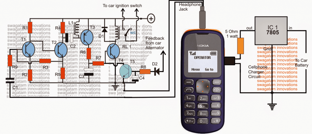
The design is basically a transistorized audio amplifier circuit, which is positioned for amplifying the assigned ringtone from the adjoining cell phone modem. The cellphone shown with the circuit stays permanently attached with the circuit and forms the integral part of the whole system.
The diagram shows a NOKIA 1280 cellphone as the modem, however any cheap cellphone may be employed for the purpose provided the cellphone includes the "assign tone" feature discretely for the particular selected numbers.
The number of the owner or the user is first stored and assigned with a suitable ringtone available within the cellphone modem so that the modem responds only to the owners phone and not to any other irrelevant numbers. The default ringtone of the modem is set to "empty" in order to mute all other unwanted calls.
When the owner calls the modem cellphone, the ringtone is detected by the circuit and amplified to a level sufficient for the relay to get energized. The relay stays energized for so long as the call remains connected.
Configuring the Relay Contacts
Since the relay contacts are configured or integrated with the ignition switch of the car, immediately triggers the ignition system of the vehicle starting the engine and the whole system.
A feed back from the activated alternator makes sure that the relay is instantly shut off irrespective of the call duration from the owner's cellphone.
The car ignition thus is able to start without the owner or the driver having to get inside the car and go through the manual operations. The car starts remotely through the owner's cell phone, a fail proof and a foolproof procedure yet as cheap as anybody can think of.
Parts List
- R1 = 22k
- R2 = 220 Ohms,
- R3 = 100K,
- R4,R6,R7 = 4K7
- R5 = 1K
- R8 = 33K
- R13 = 100 ohms,
- T1, T2, T4, T5 = BC547
- T3 = BC557,
- C1 = 0.22uF
- C2,C3, C4 = 100uF/25v
- D1, D2 = 1N4007
- L1 = 40 mH coil, example: a piezo buzzer coil will do.
- diode = 1N4007
- Relay = 12V/SPDT
- Modem = NOKIA 1280
The charger section is shown in the diagram, and needs to remain connected permanently with the attached cellphone modem.


Comments
What the L1 do when circuit is activated?
.Dear Swagatam,
I have you used NOKIA 1280.
The circuit energizes the relay as soon as I put the power on and deenergizse agin.
It also energizes the relay if I touch the input wire of the capacitor C1.
thank you
Dear Sasa,
There's certainly something not correct in your circuit, I have built so many prototypes so far and all have worked perfectly, touching the input wire should not disturb the circuit operations.
what did you use for L1?
This circuit is very sensitive that drives the relay during mobile charging.
Can you please reduce the sensitivity of the circuit to drive the relay during the ring only??
Dear Sasa,
In my circuit I did not have any such problems, so it would be difficult for me to troubleshoot…have you used NOKIA 1280 or NOKIA 1200 for testing it? I tested the design with these phones as modems and it worked flawlessly
Dear Swagatam
I have connected the relay across T3 collector/ground and eliminated the entire T4 stage.
but the relay does not energized
can you please help me
thank you very much
Dear Sasa, I did not face such problems in my circuit so it would be difficult for me to troubleshoot your circuit. For me L1 completely solved the relay triggering problem which was occurring every time the charging was being initiated internally.
for reducing sensitivity you can try connecting the relay across T3 collector/ground and eliminate the entire T4 stage.
Dear Swagatam Majumdar
I have included L1 from the beginning.
When I connected a 0.1 uF parallel with L1 the circuit increased sensitivity and relay 1 energised as soon as I turn the power on.
I cant reduce the sensitivity , What can I do ?
Please help me.
thank you
Did you include L1? Please also connect a 0.1uF capacitor parallel to L1…these two will take care of any spurious activation of the relay.