In this article I will comprehensively explain how to cascade many 4033 ICs together for driving multiple 7 segment counter displays.
In one of my previous articles I have uniquely explained the role of pin#3 and pin#4 which become crucial when the IC 4033 are intended to function for driving multiple displays.
Multiple Digit Display
I tried a lot to find a suitable IC 4033 multiple digit display circuit on the net which could show the correct method of configuring these pinouts of the IC, but I was surprised and sad to see that nobody not even the relevant datasheets explained how these needed to be wired.
You will come across many sites explaining how to cascade IC 4033, however you will find the information presented there are so mediocre and incomplete.
Therefore I sat down to study the concept myself and after a little brain storming figured out the exact method of cascading many IC 4033 for applying them with any required numbers of displays.
All other pinouts except pin#3 and pin#4 are pretty easy to understand and are are configured in a standard mode for all types of of counter configurations.
However pin#3 and pin#4 of the IC require special attention when multiple digit displays are involved in large counter circuits.
Ripple Blanking Pinouts
According to the datasheets of the IC 4033, pin#3 and pin#4 of this IC are the ripple blanking IN and ripple blanking OUT pinouts of the IC.
So I have explained the importance of the above pinouts when applied in multi-digit display counter circuits:
As explained in my previous article, in multi-digit displays for enabling the RBI and the RBO (pin#3/#4) correctly on the integer side, we need to connect RBI of the IC associated with the most significant digit to a low logic or ground and the RBO of that IC to the preceding lower significant IC’s RBI.
This should continued until we reach the first IC associated with the extreme left digit of the integer side.
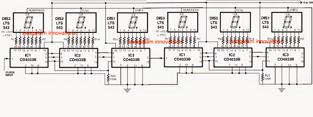
The above explanation can be better understood by looking at the following figure which shows the correct method of cascading the IC 4033. Here I have shown 6 nos of IC 4033 cascaded with each other for driving six discrete 7 segment displays.
Here I have assumed the decimal point to be after three displays, therefore here on the integer side the most significant digit is the one that's immediately on the left hand side of the decimal. therefore as per the explanation pin#3 of the IC associated with this most significant digit is connected with ground.
Next as per the above explanation, the pin#4 of the same IC is linked with the next lower significant digit's IC which immediately on the left of the above explained most significant IC, and the process is repeated until the extreme left IC which is the least significant on the integer side is reached.
Pin#4 of the above the least significant integer side IC is kept open as its irrelevant in the design.
Now let's focus on the fractional side of the display.
As per my earlier explanation here the least significant digit is the one situated at the extreme right hand side that is the sixth display at the right in the array.
Cascading with Least Important Digit
As discussed earlier pin#3 of the IC associated with this least important digit on the fractional side is kept grounded, while its pin#4 is connected with pin#3 of the IC which is immediately at the left of this IC and is repeated so forth until the IC associated with the digit display touching the right hand side of the decimal point.
The above method can be employed for cascading any number of ICs for driving the corresponding number of displays in the system.
Cascading the ICs in the said manner eliminates all the unnecessary zeros in the display which may have otherwise caused undesirable increase in the power consumption.
For example in a hand calculator we initially see only one zero at the extreme right, instead of 8 zeros over the entire display, which is also technically correct but is irrelevant and could be a nuisance in terms of power consumption.
Circuit Diagram

Comments
I request to provide a circuit 4 digit counter using thumbnail switch.
OK I will try!
Dear, Swagatam I am ajith, and thanks for your reply for programable timer, and again thank, and happy day
You are welcome Ajith…
Dear Swagatam, I came across an unknown object that only your vast electronic culture can know … from the outside it looks like a simple knob but it is in fact an endless selector with small internal notches that establish various discrete positions, not continue … and connected with a decoder that commands 2 display 7seg 0-99 … turning to the right increments of 1 unit each notch… while to the left the decrease … you can give me information about both the component and a hypothetical connection with the ic decoder? Thank you. Claudio ?
Hi Claudio, sorry I have never used or investigated this type of device so far, so can’t really say what exactly it is.
Hi Swagatam ?… rotating this ‘selector’ you can perceive small shots … but it has no limit switch … like a combinatorial safe knob … the connected circuit ‘feels’ the rotation direction … anyway … I think that your enlightened opinion on how to ‘decode’ a combinatorial knob would enrich your extensive review of circuits … thanks for all your ideas … Claudio ?
Hi Claudio, I may have to investigate the theory deeper to be able to answer you, at the moment I do not have much about it.
How do the reset buttons work on this?