Here we are talking about one circuit which many people know by the name Blood Electrification Unit, and this circuit became known because of Bob Beck many years back in the 1990s time, so now people also call it Beck Blood Electrifier.
This unit is nothing complicated looking but the idea sounds heavy because it uses a very low frequency and very low current electrical signal, and this signal is applied from outside the body using electrodes, so it does not go inside directly.
Usually these electrodes are placed on the wrist area, above the big blood vessels, so that the signal can pass through the blood area easily.
Bob Beck already said clearly that this device is not a medical treatment device and it is not medicine, but it is only an experimental bio electrical signal generator which came from some early laboratory thinking.
The circuit diagram shown here is a full working version of this idea and it is built using simple analog parts, mainly the LM358 operational amplifier so now even normal electronics learners can understand it.
General Concept Of Blood Electrification
The main idea of blood electrification is actually very simple but people feel confused when they hear the name first time.
A very low frequency square wave signal is passed through the body using electrodes but the current is kept very very small, usually in microamp level, so that it does not hurt or shock.
Bob Beck said that the frequency should be around 4 Hz and this value comes because it is half of the Earth Schumann resonance frequency which is around 7.83 Hz, so now that relation is used.
According to Bob Beck, the goal was not to stimulate tissue or give shock but only to put a gentle changing electrical field into the blood stream.
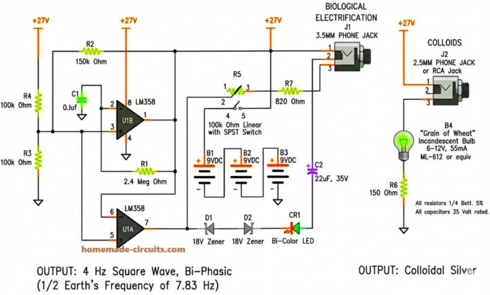
The circuit diagram attached is made exactly for this reason so it creates a low frequency bi phasic square wave output, nothing much aggressive.
Overview Of The Circuit Diagram
When we look at the circuit diagram slowly then we can see that it is divided into different sections, so now understanding becomes easier.
- One part is power supply section.
- One part is oscillator and waveform making section.
- One part is output current limiting and protection section.
- One part is electrode output connection section.
All these sections work together and since they are connected properly, so now the signal stays low frequency, stable, current limited and also safe from dangerous electrical levels.
Power Supply Arrangement
This circuit uses three 9 V batteries, marked as B1, B2, and B3. These batteries are connected in series, so the voltage becomes higher, but still the system runs only on batteries.
This point is very important because Bob Beck clearly said that battery power must be used, since if mains power is used then there is danger.
The batteries give around 27 V DC and this voltage is used to run the LM358 op amps and the output part.
Even though the voltage looks big, the current is strongly limited so now the user never feels strong current.
Oscillator And Square Wave Generator
The main working part of the circuit is made using two sections of the LM358 dual operational amplifier, named U1A and U1B. These two op amps are set as a low frequency oscillator.
Resistors R1, R2, R3, and R4, along with capacitor C1, decide how fast the signal changes.
The values are chosen so that the frequency comes near 4 Hz which means the signal changes polarity four times in one second, so now a bi phasic square wave is produced.
The waveform here is square wave and not sine wave. Bob Beck wanted square wave because it has fast rising and falling edges, and according to him this was important.
The output of U1A and U1B goes positive and negative again and again, with respect to ground.
Frequency Adjustment And Control
In the diagram, resistor R5 is shown as a 100 k Ohm potentiometer and it also has an SPST switch. This allows small adjustment of frequency around 4 Hz, so now tuning becomes possible.
This adjustment is needed because real components never have exact values and since tolerance exists, so frequency can move a little. This potentiometer helps bring it back.
The switch on R5 allows the user to turn the output on or off, without removing battery power.
Bi Phasic Output And Signal Conditioning
After the square wave is created, then signal goes through some extra parts for safety.
Diodes D1 and D2 are 18 V Zener diodes, and they act like limiters. If suppose something goes wrong then these diodes stop the voltage from going too high.
CR1 is a bi color LED and it shows the signal working. When the polarity changes then the LED color also changes, so now the user can see activity.
Capacitor C2 helps to smooth things a little, so sharp spikes do not reach the electrodes.
Current Limiting And Safety
Current limiting is the most important part of this circuit. Resistors like R6 and R7 are put in series with the output so the current always stays very small, in microamp level.
This is important because the human body is sensitive and Bob Beck strongly said that the current must stay far below any dangerous or noticeable level.
The circuit is designed so that if the electrodes touch each other then the current still does not rise to harmful value, so that safety is always there.
Electrode Output Connections
The output goes to phone jacks marked as J1 and J2. These jacks allow wrist straps or hand electrodes to be connected.
Bob Beck suggested placing electrodes on the wrists, above radial and ulnar arteries so that the electrical field passes through the blood vessels.
The diagram also shows a small bulb marked as B4. This bulb is sometimes used for showing load or for demo, but it is not needed for real operation.
Operating Principle In Simple Words
When the unit is turned on then the oscillator starts making a slow 4 Hz square wave. The signal goes positive and negative again and again.
This signal passes through current limiting and protection parts before reaching electrodes. When electrodes are placed on the body then a very small changing electrical field is formed across tissue and blood vessels.
The current stays very low, and since it uses batteries only, so now it is isolated from mains power.
Important Disclaimer
It must be clearly said that this circuit is shown only for learning and history interest.
Bob Beck said that this is not a medical device and it is not meant to treat, cure, or prevent any disease.
If someone studies or builds this circuit then it should be treated only as an experimental low frequency signal generator and not as medical replacement.
Conclusion
The Blood Electrification Unit by Bob Beck is basically a low frequency bi phasic square wave generator, with strong current limiting and battery isolation. The circuit uses LM358 op amps, Zener diodes, and resistors to keep the output safe and stable.
From electronics side this circuit is interesting because it shows how simple analog parts can make very low frequency signals safely. Whether someone studies it for learning, curiosity, or analog practice, this design still stays as an example of low frequency bio electrical experiment.


Need Help? Please Leave a Comment! We value your input—Kindly keep it relevant to the above topic!