This project explains how to build a fully automatic ultrasonic water level controller where the water pump motor starts automatically when the tank level goes below a preset LOW level and stops automatically when the tank becomes FULL. The whole system is wireless, reliable, and there are no corrosion problems because the ultrasonic sensor never touches the water at any point.
Design Used In The System
The design uses an HC-SR04 ultrasonic sensor to measure the water level, Arduino units at both Tx and Rx sides for processing, nRF24L01 RF modules for wireless communication between tank and pump, a relay driver stage to control the water pump motor, and LED indicators with a buzzer to show visual and audible status.
Why Ultrasonic Water Level Sensing
Traditional water level systems using float switches or probe-based sensors usually suffer from corrosion, scaling buildup, mechanical wear, and false triggering over time.
An ultrasonic sensor avoids all these problems because it does not come in contact with water. It simply measures the distance from the sensor to the water surface, and the Arduino then converts this distance value into the actual water level.
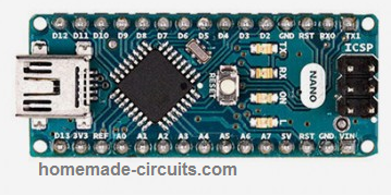
We use Arduino nano here for this project:
Transmitter Circuit Diagram
System Overview
The system is divided into two main parts, one at the tank side and the other at the pump side.
Transmitter Unit Tank Side
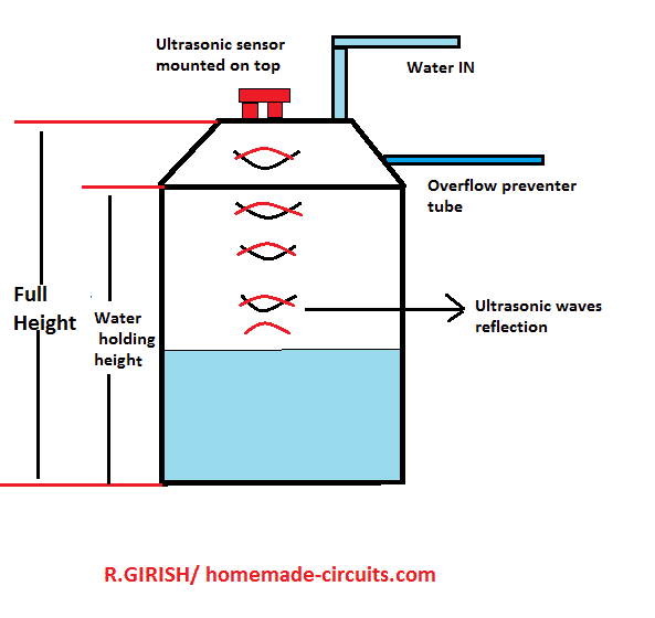
At the tank side, the ultrasonic sensor is mounted at the top of the tank facing the water surface. The Arduino measures the water level using the sensor data and then sends the water level status wirelessly to the receiver unit.
Receiver Unit Pump Side
At the pump side, the receiver unit receives the water level status data. Based on this information, it controls the LED indicators and buzzer and also drives a relay to switch the water pump ON or OFF automatically.
Transmitter Code (Tank Side)
// ----------- Program Developed by Homemade-circuits.com ----------- //

#include <SPI.h>
#include <RF24.h>

// nRF24L01 pins: CE = 9, CSN = 10
RF24 radio(9, 10);

// RF address (must match receiver)
const byte address[6] = "00001";

// Ultrasonic sensor pins
const int trigger = 3;
const int echo = 2;

// Messages to be transmitted
const char text_stop[] = "STOP";   // Tank FULL → Pump OFF
const char text_full[] = "FULL";
const char text_3by4[] = "3/4";
const char text_half[] = "HALF";
const char text_low[]  = "LOW";    // Tank LOW → Pump ON

// -------- USER CALIBRATION SECTION -------- //
// Actual usable water depth inside tank (meters)
float water_hold_capacity = 1.0;

// Total distance from ultrasonic sensor to tank bottom (meters)
float full_height = 1.3;
// ------------------------------------------ //

// Level thresholds
float level_full;
float level_3by4;
float level_half;
float level_quarter;

// Ultrasonic variables
long pulse_time;
float distance_cm;
float distance_m;
float water_level;
float offset_distance;

void setup()
{
  Serial.begin(9600);

  pinMode(trigger, OUTPUT);
  pinMode(echo, INPUT);
  digitalWrite(trigger, LOW);

  // nRF24L01 initialization
  radio.begin();
  radio.openWritingPipe(address);
  radio.setChannel(100);
  radio.setDataRate(RF24_250KBPS);
  radio.setPALevel(RF24_PA_MAX);
  radio.stopListening();   // Transmitter mode

  // Calculate level thresholds
  level_full    = water_hold_capacity;
  level_3by4    = water_hold_capacity * 0.75;
  level_half    = water_hold_capacity * 0.50;
  level_quarter = water_hold_capacity * 0.25;

  // Sensor mounting compensation
  offset_distance = full_height - water_hold_capacity;

  Serial.println("Ultrasonic Water Level Transmitter Ready");
}

void loop()
{
  delay(5000);   // Measurement interval

  // Trigger ultrasonic pulse
  digitalWrite(trigger, HIGH);
  delayMicroseconds(10);
  digitalWrite(trigger, LOW);

  // Read echo pulse
  pulse_time = pulseIn(echo, HIGH, 30000); // timeout safety

  if (pulse_time == 0)
  {
    Serial.println("Sensor Error");
    return;
  }

  // Convert pulse time to distance
  distance_cm = pulse_time * 0.034 / 2;
  distance_m  = distance_cm / 100.0;

  // Convert distance to actual water level
  water_level = water_hold_capacity - (distance_m - offset_distance);

  if (water_level < 0)
    water_level = 0;

  if (water_level > water_hold_capacity)
    water_level = water_hold_capacity;

  // Debug output
  Serial.print("Water Level: ");
  Serial.print(water_level);
  Serial.println(" m");

  // -------- TRANSMISSION LOGIC -------- //

  if (water_level >= level_full)
  {
    radio.write(&text_stop, sizeof(text_stop));  // Pump OFF
    Serial.println("TX: STOP");
  }
  else if (water_level > level_3by4)
  {
    radio.write(&text_full, sizeof(text_full));
    Serial.println("TX: FULL");
  }
  else if (water_level > level_half)
  {
    radio.write(&text_3by4, sizeof(text_3by4));
    Serial.println("TX: 3/4");
  }
  else if (water_level > level_quarter)
  {
    radio.write(&text_half, sizeof(text_half));
    Serial.println("TX: HALF");
  }
  else
  {
    radio.write(&text_low, sizeof(text_low));    // Pump ON
    Serial.println("TX: LOW");
  }

  Serial.println("-----------------------------");
}

// ----------- Program Developed by Homemade-circuits.com ----------- //
Why this transmitter code looks great
Simple reason, it does ultrasonic conversion properly, so readings stay accurate, and it does what it is supposed to do.
Here tank size does not really matter here, you just change two values and it is done. No need to redesign anything, so it fits small tank big tank, whatever you have.
There is timeout protection also, so if sensor fails or gets stuck then system does not keep waiting indefinitely, it safely exits.
Relay chattering is avoided in this design, switching happens only at LOW and FULL, not in between, so relay stays calm without any clicking noise, so there is no damage over time.
This code works fully with the receiver and relay logic given below.
Important installation tip,
Sensor must face straight down, do not tilt it, otherwise readings could go wrong.
Keep around 5–10 cm clearance from tank walls, since reflections can confuse the sensor, and then values can jump.
Please avoid steam and water droplets on sensor face because that can finish of accuracy fast, and then system starts behaving rather weird.
Receiver Stage Wiring Connection Table (For Drawing Schematic)
You can literally draw the full receiver side schematic from this table.
We use Arduino NANO for the wiring:
| Arduino Nano Pin | Connected To |
|---|---|
| D2 | LOW LED |
| D3 | HALF LED |
| D4 | 3/4 LED |
| D5 | FULL LED |
| D6 | Buzzer |
| D7 | Relay driver input |
| D9 | nRF24 CE |
| D10 | nRF24 CSN |
| D11 | nRF24 MOSI |
| D12 | nRF24 MISO |
| D13 | nRF24 SCK |
| 5V | Relay, LEDs, buzzer |
| 3.3 V | nRF24 VCC |
| GND | Common ground |
Receiver Code With Automatic Pump Control
Below is the receiver code with an added relay output for the motor.
Receiver Code
#include <SPI.h>
#include <RF24.h>

RF24 radio(9, 10);

const byte address[6] = "00001";

const int buzzer = 6;
const int LED_full = 5;
const int LED_three_fourth = 4;
const int LED_half = 3;
const int LED_quarter = 2;
const int relay_pin = 7;   // Pump relay

char text[32] = "";

void setup()
{
  pinMode(buzzer, OUTPUT);
  pinMode(LED_full, OUTPUT);
  pinMode(LED_three_fourth, OUTPUT);
  pinMode(LED_half, OUTPUT);
  pinMode(LED_quarter, OUTPUT);
  pinMode(relay_pin, OUTPUT);

  digitalWrite(relay_pin, LOW);   // Pump OFF at power ON

  digitalWrite(buzzer, HIGH);
  delay(300);
  digitalWrite(buzzer, LOW);

  Serial.begin(9600);

  radio.begin();
  radio.openReadingPipe(0, address);
  radio.setChannel(100);
  radio.setDataRate(RF24_250KBPS);
  radio.setPALevel(RF24_PA_MAX);
  radio.startListening();
}

void loop()
{
  if (radio.available())
  {
    radio.read(&text, sizeof(text));
    Serial.println(text);

    // ---------- STOP / FULL ----------
    if (text[0] == 'S' || (text[0] == 'F' && text[1] == 'U'))
    {
      digitalWrite(relay_pin, LOW);   // Pump OFF

      digitalWrite(LED_full, HIGH);
      digitalWrite(LED_three_fourth, HIGH);
      digitalWrite(LED_half, HIGH);
      digitalWrite(LED_quarter, HIGH);
    }

    // ---------- LOW ----------
    if (text[0] == 'L' && text[1] == 'O' && text[2] == 'W')
    {
      digitalWrite(relay_pin, HIGH);  // Pump ON

      digitalWrite(LED_full, LOW);
      digitalWrite(LED_three_fourth, LOW);
      digitalWrite(LED_half, LOW);
      digitalWrite(LED_quarter, HIGH);
    }

    // ---------- INTERMEDIATE LEVELS ----------
    if (text[0] == '3')
    {
      digitalWrite(LED_full, LOW);
      digitalWrite(LED_three_fourth, HIGH);
      digitalWrite(LED_half, HIGH);
      digitalWrite(LED_quarter, HIGH);
    }

    if (text[0] == 'H')
    {
      digitalWrite(LED_full, LOW);
      digitalWrite(LED_three_fourth, LOW);
      digitalWrite(LED_half, HIGH);
      digitalWrite(LED_quarter, HIGH);
    }
  }
}
Relay and Pump Wiring Details
Use a ready-made opto-isolated relay module, that is better and safer.
Relay COM goes to Phase input, then Relay NO goes to pump phase wire, so pump switches ON and OFF from relay.
Neutral wire goes directly to pump, no switching there. Mains voltage is dangerous, so if you are unsure at any point, then consult a qualified electrician, do not take risk.
Ultrasonic Sensor Mounting Tips
Mount the HC-SR04 exactly at the center of the tank lid, not here and there. Keep minimum 5–10 cm clearance from walls, otherwise readings go wrong.
Avoid tilted mounting, sensor must face straight down.
Do not allow water droplets on sensor face, since that will confuse the echo.
Advantages of This Design
No water contact sensors, so nothing corrodes. Long wireless range, works comfortably. Fully automatic, no manual switching. No false triggering, readings stay stable.
Suitable for overhead tanks, common use. Easily expandable, you can add more features later.
Wrapping Up
This ultrasonic water level controller is reliable, scalable and works well for domestic and industrial water tanks. With simple parameter changes in the code, the same design can be used for any tank height or shape, so no redesign needed.
If you build this project, then feel free to share your experience or ask for modifications in the comments.


Need Help? Please Leave a Comment! We value your input—Kindly keep it relevant to the above topic!