In this post we are going to make a simple but useful circuit that can make an RGB LED glow in a nice flowing way. That is not just random blinking, but smooth sequential lighting of red, green, and blue one by one.

This is done using Arduino, so you need to have some basic knowledge of Arduino programming and connections but do not worry, we will explain everything slowly step by step.
So this circuit is called Arduino RGB Sequential Light Generator Circuit and its main purpose is to make a connected RGB LED show a smooth flowing pattern of red, green, and blue lights. The pattern will repeat continuously, making a nice visual effect.
LED Type and Connection Details
We must be very clear about the type of RGB LED we are using here. The LED is a four pin type and rated for 30 mA current.
Important point is that it is a common anode type LED. That means the common pin of this RGB LED must always be connected to positive voltage, like +5V from Arduino.
Then the red, green, and blue pins of the LED will be connected to Arduino output pins via current limiting resistors.
But if you use a common cathode type RGB LED instead then the common pin must be connected to ground (GND). Many beginners get confused between common anode and common cathode, so let us stress it again:
- Common anode → Common pin to +5V
- Common cathode → Common pin to GND
If you connect them the wrong way then LED will not glow as expected.
Required Hardware Components
Now let us list the full hardware needed for building this circuit, so that you do not forget anything:
- One Arduino UNO Board. This is the brain of the project that will control the sequence of RGB illumination.
- One 220 Ohm 1/4 Watt Resistor. These resistors are important to limit current going into the RGB LED pins, because direct connection may burn the LED.
- One RGB 5mm 30mA LED of Common Anode Type. Make sure it is not common cathode type, because our circuit is designed for common anode.
- Link Wires. These are needed to make connections between Arduino and the LED circuit.
- Soldering Iron. If you want to make the circuit permanent on a PCB or perf board then soldering iron will be needed, otherwise for testing, jumper wires are enough.
- 9V Adapter AC/DC Power Supply. This will power the Arduino when not connected to PC via USB.
How It Works
Now, when we power the Arduino and upload the controlling code, then Arduino will turn on Red LED first by setting corresponding pin to LOW (since common anode needs positive supply and individual pins pulled low to glow). After some delay, Arduino will turn off Red and turn on Green and then after another delay, turn off Green and turn on Blue. This cycle will repeat forever, making the RGB LED glow in smooth flowing sequence of Red → Green → Blue → Red → and so on.
So this simple but interesting project is useful for visual learning of Arduino control, understanding LED current limitations, and making decorative lighting patterns.
That is all for now. Let us build and test this simple but fun Arduino RGB Sequential Light Generator circuit.
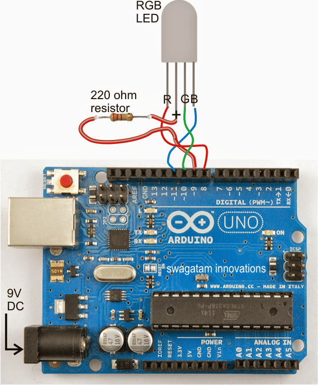
RGB LED Sequential Light Circuit Connection Details
Now we are going to talk about the connection details of this proposed RGB LED sequential light circuit using Arduino. You can see the full connection diagram in the above image.
But let us explain it in words, so that even if you do not understand diagrams, you can still build it.
The connections are very simple and easy to implement. That means you just have to insert the LED leads into Arduino board’s pinouts directly. Then connect the power socket properly and switch ON the power supply. After this, you will be able to see the RGB LED start working, running in sequence – first red illuminates, then green, and after that blue.....all flowing smoothly one by one in a continuous manner.
Since the code is fully customizable, so you can change the speed, brightness, and color flow order as per your own individual preferences and personal selection. That is the nice part of using Arduino. You can modify the code later when you feel like, and experiment with it.
Arduino Sketch Code for RGB LED Sequential Flowing Light
So here is the sketch code for this RGB LED sequential flowing light circuit that you can use directly or modify as you wish:
/*
RGB LED color flow
Displays a [fairly] smooth
sequence of colors on an RGB LED

by Jeremy Fonte
Copyright (c) 2012 Jeremy
Fonte. All rights reserved.
This code is released under the
MIT license:

https://opensource.org/licenses/MIT
*/

int r = 0;
int g = 0;
int b = 0;

int ri = 1;
int gi = 3;
int bi = 2;

// the setup routine runs once when you press reset:
void setup() {
    // initialize the digital pin as
    // an output.
    pinMode(8, OUTPUT);
    pinMode(9, OUTPUT);
    pinMode(10, OUTPUT);
    pinMode(11, OUTPUT);

    digitalWrite(9, HIGH);
}

// the loop routine runs over and over again forever:
void loop() {
    r = r + ri;
    g = g + gi;
    b = b + bi;

    if(r > 255) {
        r = 255;
        ri = -1 * random(1, 3);
    }
    else if(r < 0) {
        r = 0;
        ri = random(1, 3);
    }

    if(g > 255) {
        g = 255;
        gi = -1 * random(1, 3);
    }
    else if(g < 0) {
        g = 0;
        gi = random(1, 3);
    }

    if(b > 255) {
        b = 255;
        bi = -1 * random(1, 3);
    }
    else if(b < 0) {
        b = 0;
        bi = random(1, 3);
    }

    analogWrite(8, r);
    analogWrite(10, g);
    analogWrite(11, b);
    delay(20);
}
So now once you upload this code to Arduino and connect the circuit properly then RGB LED will start flowing smoothly in colors. That means red, green, and blue will flow one by one repeatedly, giving nice color changing effect.
Let us try this simple but fun Arduino project since it is helpful to understand basic Arduino coding, RGB LED working principle and how to control analogWrite PWM for LED brightness control. Now this is really cool project for learning and decoration purpose at the same time.

Need Help? Please Leave a Comment! We value your input—Kindly keep it relevant to the above topic!