• Skip to main content
  • Skip to primary sidebar

Homemade Circuit Projects

Need circuit help? Post them in the comments! I've answered over 50,000!

Blog | Categories | About | Contact | Calculators-online
You are here: Home / Inverter Circuits / Adjustable RMS Modified Inverter Circuit using BJTs

DIY Circuits | Learn Basics | Arduino Coding


Adjustable RMS Modified Inverter Circuit using BJTs

Last Updated on September 26, 2025 by Swagatam Leave a Comment

A very interesting circuit of a RMS controlled modified sine wave inverter is discussed in this article which incorporates just ordinary transistors for the proposed implementations.

The use of transistors typically makes the circuit easier to understand and more friendly with the new electronic enthusiasts. The inclusion of a PWM control in the circuit makes the design very efficient and desirable as far as operations of sophisticated appliances are concerned at the inverter output.

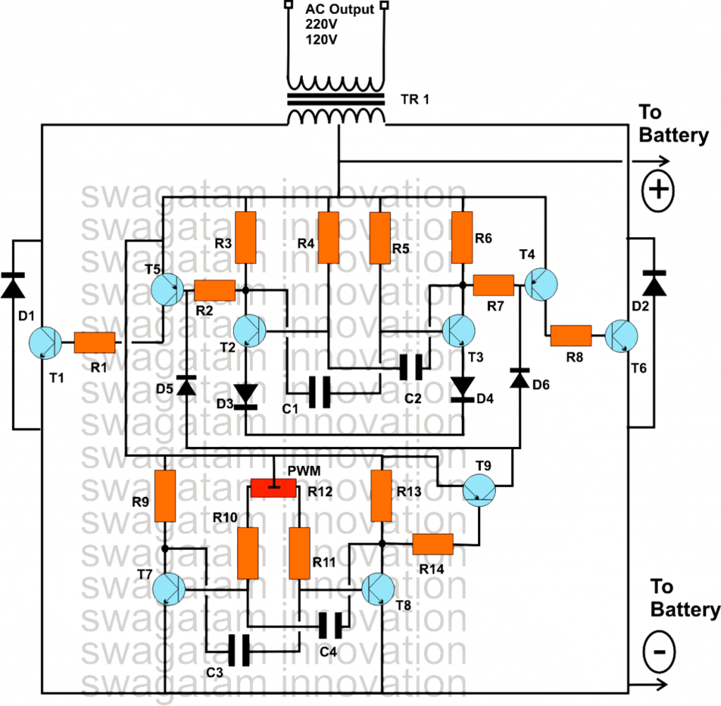
The circuit diagram shows how the entire circuit is laid down. We can clearly see that only transistors have been involved and yet the circuit can be made to produce well-dimensioned PWM controlled waveform for generating the required modified sinew waveforms or rather modified square waves to be more precise.

The whole concept may be understood by studying the circuit with the help of the following points:

Astable as the Oscillators

Basically we can witness two identical stages which are wired up in the standard astable multivibrator configuration.

Being astable in nature the configurations are specifically intended for generating free running pulses or square wave at their respective outputs.

However the upper AMV stage is positioned for generating the normal 50 Hz (or 60 Hz) square waves which are used for operating the transformer and for the required inverter actions, in order to get the desired AC mains power at the output.

Therefore there’s nothing too serious or interesting about the upper stage, typically it consists a central AMV stage consisting of T2, T3, next comes the driver stage consisting of the transistors T4, T5 and finally the receiving output stages consisting of the T1 and T6.

How the Output Stage Works

The output stage drives the transformer via the battery power for the desired inverter actions.

The above stage is only responsible for carrying out the generation of the square wave pulses that’s imperatively required for the intended normal inverting actions.

The PWM Chopper AMV Stage

The circuit at the lower half is the section which actually does the sine wave modifications by switching the upper AMV according to its PWM settings.

Precisely, the upper AMV stage’s pulse shape is controlled by the lower AMV circuit and it implements the square wave modification by chopping the basic square inverter square waves from the upper AMV into discrete sections.

The above chopping or dimensioning is executed and defined by the setting of the preset R12.

R12 is used for adjusting the mark space ratio of the pulses generated by the lower AMV.

According to these PWM pulses, the basic square wave from the upper AMV is chopped into sections and the average RMS value of the generated waveform is optimized as close as possible to a standard sine waveform.

150 Watt Modified Sine Wave Inverter Circuit Using only Transistors

The remaining explanation regarding the circuit is pretty ordinary and may be done by following the standard practice that’s normally employed while building invertes, or for that matter, my other related article may be referred for acquiring the relevant information.

Parts List

  • R1, R8 = 15 Ohms, 10 WATTS,
  • R2, R7 = 330 OHMS, 1 WATT,
  • R3, R6, R9, R13, R14 = 470 OHMS ½ WATTS,
  • R4, R5 = 39K
  • R10, R11 = 10K,
  • R12 = 10K PRESET,
  • C1-----C4 = 0.33Uf,
  • D1, D2 =1N5402,
  • D3, D4 = 1N40007
  • T2, T3, T7, T8= 8050,
  • T9 = 8550
  • T5, T4 = TIP 127
  • T1, T6 = BDY29
  • TRANSFORMER = 12-0-12V, 20 AMP.
  • T1, T6, T5, T4 SHOULD BE MOUNTED OVER SUITABLE HEATSINK.
  • BATTERY = 12V, 30AH

You'll also like:

  • weldingMini Welding Machine Circuit for Small Welding Jobs
  • convert h bridge to sine wave h bridge basic layoutConvert any H-Bridge Inverter to Sine Wave H-bridge Inverter
  • Optimizing Grid, Solar Electricity with Inverter
  • Automatic Inverter Fan Switch ON while Charging and Inverting Modes

Filed Under: Inverter Circuits Tagged With: Adjustable, BJTs, Inverter, Modified, RMS

About Swagatam

I am an electronics engineer and doing practical hands-on work from more than 15 years now. Building real circuits, testing them and also making PCB layouts by myself. I really love doing all these things like inventing something new, designing electronics and also helping other people like hobby guys who want to make their own cool circuits at home.

And that is the main reason why I started this website homemade-circuits.com, to share different types of circuit ideas..

If you are having any kind of doubt or question related to circuits then just write down your question in the comment box below, I am like always checking, so I guarantee I will reply you for sure!

Previous Post: « Modified Inverter Circuits using 4049, 4093 ICs
Next Post: Solving Darlington Transistor Formulas and Calculations »

Reader Interactions

Need Help? Please Leave a Comment! We value your input—Kindly keep it relevant to the above topic! Cancel reply

Your email address will not be published. Required fields are marked *

Primary Sidebar

circuit simulator image


Subscribe to get New Circuits in your Email


Categories

  • Arduino Projects (95)
  • Audio and Amplifier Projects (133)
  • Automation Projects (18)
  • Automobile Electronics (103)
  • Battery Charger Circuits (87)
  • Datasheets and Components (109)
  • Electronics Theory (149)
  • Energy from Magnets (27)
  • Games and Sports Projects (11)
  • Grid and 3-Phase (20)
  • Health related Projects (27)
  • Home Electrical Circuits (13)
  • Indicator Circuits (16)
  • Inverter Circuits (95)
  • Lamps and Lights (159)
  • Meters and Testers (71)
  • Mini Projects (28)
  • Motor Controller (68)
  • Oscillator Circuits (28)
  • Pets and Pests (15)
  • Power Supply Circuits (91)
  • Remote Control Circuits (50)
  • Renewable Energy (12)
  • Security and Alarm (64)
  • Sensors and Detectors (106)
  • SMPS and Converters (34)
  • Solar Controller Circuits (60)
  • Temperature Controllers (43)
  • Timer and Delay Relay (49)
  • Voltage Control and Protection (42)
  • Water Controller (37)
  • Wireless Circuits (31)


Other Links

  • Privacy Policy
  • Cookie Policy
  • Disclaimer
  • Copyright
  • Videos
  • Sitemap


People also Search

555 Circuits | 741 Circuits | LM324 Circuits | LM338 Circuits | 4017 Circuits | Ultrasonic Projects | SMPS Projects | Christmas Projects | MOSFETs | Radio Circuits | Laser Circuits | PIR Projects |

Social Profiles

  • Twitter
  • YouTube
  • Instagram
  • Pinterest
  • My Facebook-Page
  • Stack Exchange
  • Linkedin


Recent Comments

  • Swagatam on 7 Simple Continuity Tester Circuits Explained
  • Swagatam on Echo Effect Generator Circuit
  • Swagatam on Making a Cell Phone Controlled Remote Bell Circuit
  • Swagatam on Ultrasonic Fuel Level Indicator Circuit
  • Keir Vaughan-Taylor on 7 Simple Continuity Tester Circuits Explained

© 2026 · Swagatam Innovations