In this post we'll learn about a simple circuit which allows a manual adjust feature for the spark timing of a motorcycle's CDI either to achieve an advance ignition, retarded ignition or simply a normal timed ignitions.
After a comprehensive study regarding the subject I was apparently successful in designing this circuit which can be used by any motorcycle rider for achieving enhanced speed and fuel efficiency by adjusting the ignition timing of the vehicle's engine as desired, depending on its instantaneous speed.
Ignition Spark Timing
We all know that the timing of the ignition spark generated inside a vehicle engine is crucial in terms of its fuel efficiency, engine life and the speed of the vehicle, wrongly timed CDI sparks can produce a poorly running vehicle and vice versa.
The recommended igniting time for the spark inside the combustion chamber is when the piston is about 10 degrees after it has crossed the TDC (Top Dead Center) point. The pickup coil is tuned to correspond this and each time the piston reaches just before the TDC, the pickup coil triggers the CDI coil to fire the spark, termed as BTDC (before top dead center.
The combustion done with the above process generally produces a good engine functioning and emissions.
However the above works nicely only as long as the engine is running at some recommended average speed, but for motorcycles that are designed to attain extraordinary speeds the above idea starts malfunctioning and the motorcycle is inhibited from achieving the specified high speeds.
Synchronizing Spark Time with Varying Speeds
This happens because at higher speeds the piston moves much rapidly than the ignition spark can anticipate it. Although the CDI circuit initiates the triggering correctly, and tries to complement the piston position, by the time the spark is able to ignite at the spark plug, the piston has already traveled much ahead of the TDC, causing undesirable combustion scenario for the engine. This in turn results in inefficiencies, preventing the engine from attaining its specified higher speed limits.
Therefor in order to correct the ignition firing time, we need to slightly advance the spark plug firing by commanding a slightly advanced trigger for the CDI circuit, and for slower speeds this simply needs to be reversed and the firing needs to be preferably slightly retarded for allowing optimum efficiency for the vehicle engine.
We'll discuss all these parameters much elaborately in some other article, at the moment we would want to analyze the method that would allow us to achieve a manual adjustments of the ignition spark timing either to advance, retard or work normally as per the speed of the motor bike.
Pickup Timing may not be Reliable Enough
From the above discussion we can conclude that the pickup coil trigger does not solely become reliable for high speed motorcycles, and some means of advancing the pickup signal becomes imperative.
Normally this is done using microcontrollers, I have tried to achieve the same using ordinary components, apparently it looks to be a logically feasible design, although only a practical test can confirm it's usability.
Designing an Electronic CDI Advance Retard Processor
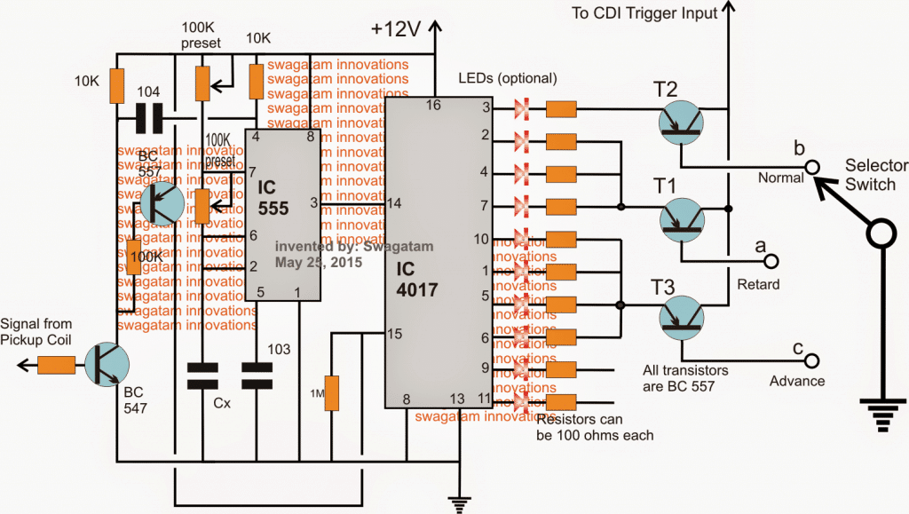
Referring to the above design of the proposed adjustable CDI spark advance and retard timer circuit, we can see an ordinary IC 555 and an IC 4017 circuit which are rigged in a standard "LED chaser light circuit" mode.
The IC 555 is set like an astable that produces and feeds clock pulses to pin#14 of the IC 4017 which in turn responds to these pulses and produces an "jumping" high logic across its output pinouts starting from pin#3 to pin#11 and then back to pin#3.
A couple of NPN/PNP BJTs can be seen on the left side of the diagram, these are positioned to reset the two ICs in response to the signals received from the motorcycles pickup coil.
The pickup coil signal is fed to the base of the NPN which prompts the ICs to reset and restart the oscillations, each time the pickup coil senses a completed revolution by the associated flywheel.
Optimizing the IC 555 Frequency
Now, the IC 555 frequency is adjusted such that by the time the pickup coil detects one revolution and resets the ICs, the 555 IC is able to produces about 9 to 10 pulses enabling the IC 4017 to render a high upto its pin#11 or at least upto its pinout#9.
The above may be set for revolutions corresponding to the idling speed of the motorcycle.
It means that during idle speeds the pickup coil signals would allow the 4017 outputs to travel through almost all the pinouts until its reset back to pin#3.
However, now let's try to simulate what would happen at higher speeds.
Response at Higher Vehicle Speed
At higher speeds the pickup signals would produce faster signals than the normal setting, and that would in turn prevent the IC 555 from generating the stipulated 10 pulses, so may be now it would be able to generate say around 7 pulses or 6 pulses at a given higher speed of the vehicle.
This in turn would prevent the IC 4017 from enabling all its output to be high, instead now it would be able to conduct only as far as pin#6 or pin#5, after which the pickup would force the IC to reset.
Dividing the Flywheel into 10 Advance/Retard Divisions
From the above discussion we can simulate a situation where at idle speeds, the outputs of the 4017 IC is dividing the pickup flywheel rotation into 10 divisions, wherein the bottom 3 or 4 pinout signals can be considered to be corresponding to the signals that may be occurring just before the actual pickup coil triggering signal, similarly the pinout high logics at pin#2,4,7 could be simulated to be the signals appearing just after the actual pickup coil triggering has gone past.
Therefore we can assume the signals at the lower pinouts of the IC 4017 to be "advancing" the actual pickup signals.
Also, since the resetting from the pickup pushes the IC 4017 high to its pin#3, this pinout can be assumed to be corresponding the pickup's normal "recommended" trigger....while the pinouts that follow the pin#3, that is the pinouts2,4,7 could be assumed to be the signals corresponding to the late signals or the "retarded" signals, with respect to the actual pickup triggers.
How to Set up the Circuit
For this we first need to know the time required by the pickup signal to generate each alternate pulses.
Suppose you record it to be around 100 millisecond (an arbitrary value), this would imply that the 555 IC needs to produce pulses at its pin#3 at the rate of 100/9 = 11.11 ms.
Once this is set, we can approximately assume the outputs from the 4017 to be producing high logic across all its outputs which would gradually "recede" as the pickup signals become faster and faster in response to the vehicle's speed.
This would induce a receding "high" logics across the bottom pinouts of the IC 4017, therefore at higher speeds the rider would get an option of manually resorting to the lower sets of pins for triggering the CDI coil, as shown in the diagram (see selector switch options).
In the figure we can see a selector switch which can be used for selecting the pinout triggers from the IC 4017 IC for triggering the CDI coil.
As explained above, the lower set of receding pinout high logics once selected, would enable an advance triggering of the CDI coil and thus allow the rider to achieve a self adjusting automatic advance firing of the CDI coil, however this must be selected only when the vehicle is running much above the recommended normal speed.
Identically if the rider contemplates a lower speed for the vehicle, he can toggle the switch for selecting the "retarded" timing option, available across the pinouts that are just after the pin#3 of the IC 4017.
During the recommended normal speeds the biker can opt for the pin#3 as the triggering output for the CDI which would allow the vehicle to enjoy an efficient ride at the given normal speeds.
The above advance/retard timing theory was inspired from the explanation as expressed in the following video:
The original video link which can be watched on Youtube, is given below:
How to Make the Above Concept Automated
In following section I have explained the method of upgrading the above concept to an automatic version using a tachometer and an opamp circuit stages. The idea was requested by Mr. Mike, and designed by Mr.Abu-Hafss.
Technical Specifications
Greetings!
Interesting stuff here, im currently laying out traces on CAD and would like to etch this on some PCB but i would rather have the selection of advance standard or retard left to electronics...
I am a bit new to this but feel as though i have a pretty good grasp on the concepts at play...
my question is, are there any articles you have on automating the advance selection based on engine RPM? oh and a parts list of the various components would be spectacular???
Thanks, Mike
The Design, by Abu-Hafss
Hi Swagatam
Referring to your article on advance, retard ignition spark CDI for enhancing high speed motorcycle efficiency, I would like to comment that I haven't yet came across any situation in which RETARDation (or more precisely DELAY) of firing of the sparks is required. As you mentioned, mostly bikes (racing bikes) fail to perform in high RPM (typically above 10,000RPM) so advance firing of spark is required. I had almost same idea in my mind, but could not test physically.
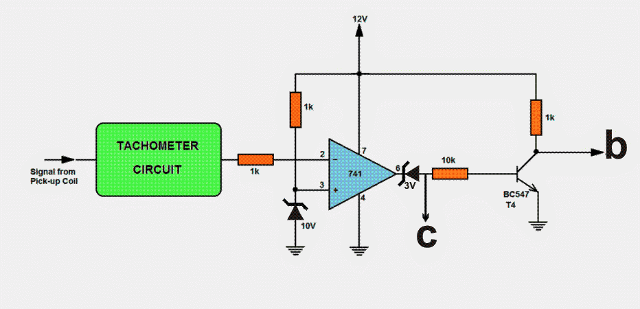
Following is my proposed addition to your circuit:
To automate the switching of firing spark between NORMAL and ADVANCE, a tachometer circuit can be used with a few more components. The voltmeter of the tachometer circuit is removed and the output is fed into pin #2 of IC LM741 which is used as a comparator. A reference voltage of 10V is assigned at pin #3. The tachometer circuit is designed to give 1V output against 1000RPM thus 10V refers to 10,000RPM. When the RPM is more than 10,000, pin #2 has more than 10V and hence the output of 741 goes low (zero).
This output is connected to the base of T2 hence, low output switches on T2. If the RPM is below 10,000 the output goes high and hence T2 switches off. At the same time T4, which is configured as signal inverter, inverts the output to low and the same is connected to the base of T3 hence, T3 is switched on.
Regards
Abu-Hafss


Comments
In the circuit the voltage pulse coming at T1/T2/T3 collecter is around 0.4 volts.Is it sufficient? (Selected Base is 0 volts,so emitter of selected transistor is at 0.7 volts.saturation voltage is around 0.3 volts)
Hello. I'm also in the process of designing a total loss ignition controlled by a micro controller.
I just wanted to let you know that as the engine RPMs increase you want to retard the timing, not advance. And conversely at lower RPMS you want your timing to be advanced. You also said "the recommended igniting time for the spark inside the combustion chamber is when the piston is about 10 degrees after it has crossed the TDC" This is not true. Ideal maximum combustion pressure occurs at 10 degrees after TDC. Ideally you want your combustion to begin around 5-20 degrees before TDC. You need to keep in mind that although piston velocity is variable, combustion speed is a constant.
Hello, I have uploaded the video from which my theory was inspired, according to this video, as the engine speed increases the spark timing must be proportionately advanced so that the combustion does not lag behind due to the delay, and the compression is able to take place at the optimal point.
May know many watt for all size of resistor ?
100K preset use the type of VR potensio or trimpot ?
What size resistor to the basic Transistor BC547 ?
And LED are used measuring how, please help Sr…!!!
all are standard parts, nothing is specific.
https://www.homemade-circuits.com/2015/09/how-to-identify-component-specs-in.html
This is over my head! But I learn as I go I want to make something like this for my bike. I will be running a turbo on my bike and I've been told 1 degree retard per psi of boost . This person told me set timming 29 degrees and run all out but it will be crap off the line . I rather have a unit that can be played with . What would it take for this to be in my hands?
the above concept will need to be first tested on a work bench, then refined, optimized, customized, and only then it could be practically implemented in a particular bike…and all these will need to be done by an expert, so at the moment it may not be recommend for any newcomer.
Wow, very very innovative,
This circuit can use for stock CDI?
Do you had test it?
How many adjust in degree if set this to advance/retard from stock/normal ignition?
Thanks a lot Mr. Swagatam
thanks, it has not been tested but I am sure, it will work, since the stages are very obvious.
However the 10 outputs from the IC4017 means only 10 divisions for the pickup cycle which can be crude, it needs to be around minimum 36 divisions which could the response much accurate…it could be achieved by cascading more number of 4017 ICs.
Tanks alot
Thi is circuuite for AC CDI or DC. CDI …sr???
it is for both
innovative , efficient and cheap solution.
thanks lot Mr Swagatam.
you are welcome expectum
Greetings!
Interesting stuff here, im currently laying out traces on CAD and would like to etch this on some PCB but i would rather have the selection of advance standard or retard left to electronics… I am a bit new to this but feel as though i have a pretty good grasp on the concepts at play… my question is, are there any articles you have on automating the advance selection based on engine RPM? oh and a parts list of the various components would be spectacular??? Thanks, Mike
Thanks for understanding and appreciating the concept!
I have not yet published the automatic version of the above, possibly I'll try to finish it soon and post it in this blog