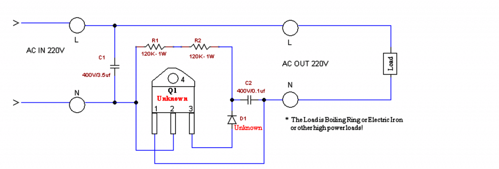
In this article I have explained an alternator power booster circuit which was unveiled by one of the keen followers of this blog, Mr Michael Mbamobi. I have explained more about the details. Technical Specifications There is this circuit I want to show you. I want to show you the circuit through Homemade Circuit or Brighthub. I […]
Newly Updated Circuit Projects:
PWM Controlled Voltage Stabilizer Circuit

In this post I have explained how to make a high power 100V to 220V H-bridge mains voltage stabilizer circuit using automatic PWM control. The idea was requested by Mr. Sajjad. Circuit Objectives and Requirements Secondary Features I like it to has an LCD to display parameters and a custom name,high voltage cut off, over […]
How to Connect 5V Single Channel Relay Module
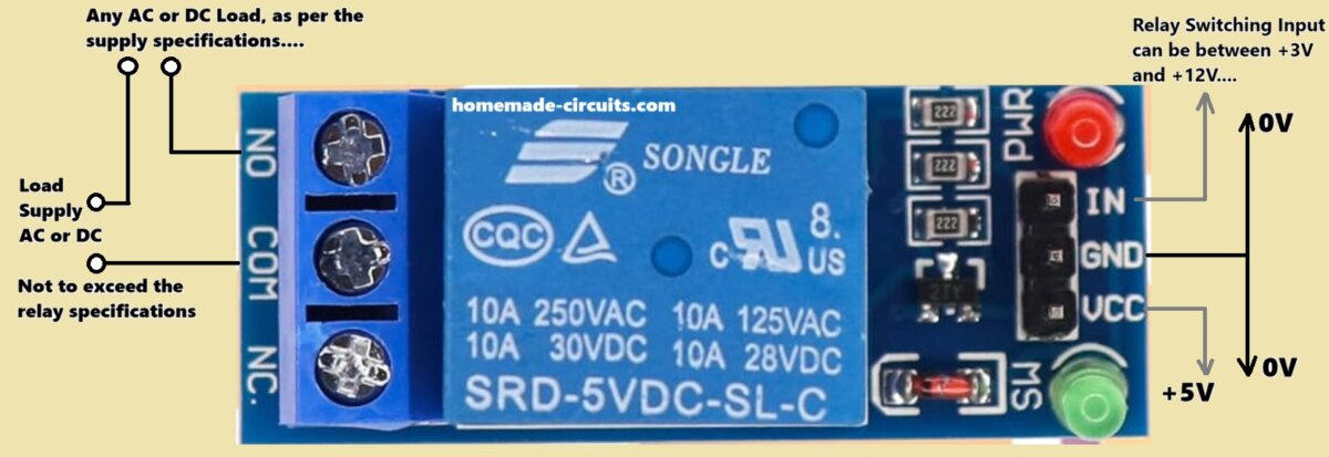
In this post we are talking about this handy little gadget called a 5V single-channel relay module. It is super useful for our microcontroller projects whether we are using Arduino, Raspberry Pi, or even the ESP8266/ESP32. Let us break it down together, what it is, how it works, and how we can connect it. Understanding […]
3 Interesting DRL (Day Time Running Light) Circuits for Your Car
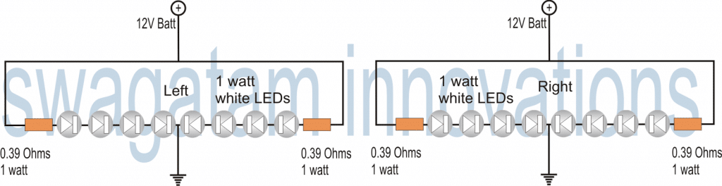
DRL or Day Time Running Lights are a chain of bright lights mostly LEDs installed just under a vehicle’s headlight, which illuminate automatically during day time to ensure that others can distinctly notice the vehicle approaching even from a distance. The following customized DRL circuit was requested by Mr. Jivesh Technical Specification as Provided by […]
5 Interesting Flip Flop Circuits – Load ON/OFF with Push-Button
Five simple yet effective electronic toggle flip flop switch circuits can be built around the IC 4017, IC 4093, and IC 4013. We will see how these can be implemented for switching a relay alternately ON OFF by alternately pressing a single push-button or through touch pads, which in turn will switch an electronic load […]
EGS002 Datasheet, Circuit Diagram Explained
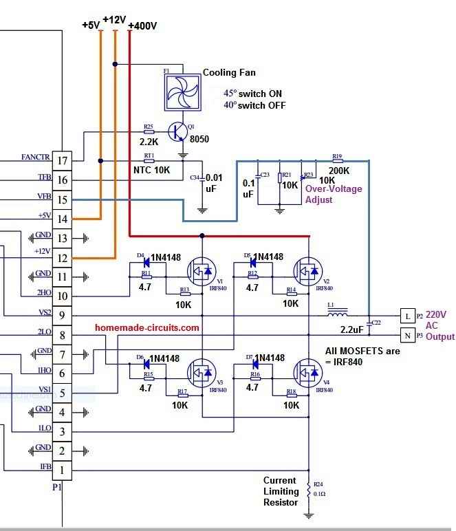
The driver board EGS002 was created especially for single-phase sinusoid inverters. It makes use of an IR2110S driver chip and an ASIC EG8010 control chip. Protection against voltage, current, and temperature is included into the driver board. LEDs are used to indicate warnings, and fan control is included. Jumpers enable the setting of dead time, […]