In this post I will show how to construct an automatic school bell/college bell system using Arduino, 16 x 2 display and real time clock module. You can program this project to ring the bell up to 16 times a day at your preferred hour and minute. The length of the bell ring can be programmed in seconds.
Looking for a simpler version without coding? Get it HERE
Overview
Gone are the days, when a peon in a school rang the bell “tin tin tin” and the students ran out of the school entrance with flying colors. Some may get even happier when the peon rang the last bell few minutes earlier.
This was the scenario 15 to 20 years ago, but now all the schools and colleges strictly time bound and the bells are automated.
Author’s quick childhood / teenage hood remember:
During my primary and secondary school the digital watch which I wore was synchronized with school’s bell system with 1 second precision.
I would yell “the bell is going to ring in 5 seconds” after the bell rang all students stare at me with surprise, this happens almost every day. On some day I and my close friends start count down 10, 9, 8, 7…..before the last bell.
All my friends say it is a magic wrist watch, but they didn’t realize one simple fact that the school bell was automated. LOL!!
We are going to make one such school/college bell using Arduino.
You may be also interested in a IC 4017 based School Bell system
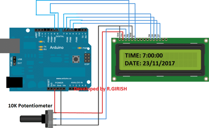
Display to Arduino Connection
The display to Arduino connections are slightly different from what we wire them usually, the pins 9, 8, 7, 6, 5 and 4 used here. The pin number 2 and 3 are used as hardware interrupt via push buttons.
Use the 10K potentiometer for adjusting the contrast for the display.
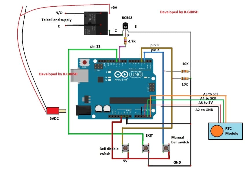
Detailed Information Regarding Bell and Relay Connections:
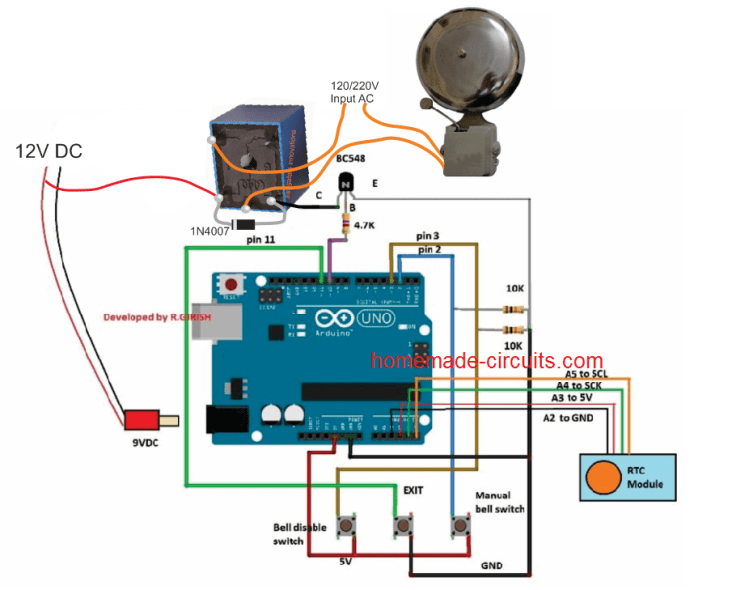
UPDATE: A5 to SCL and A4 to SDA (Not A4 to SCK)
Real Time Clock Module
The Real time clock module keeps the track of the time even after long power-cut. A 9V relay is provided for switching the bell on and off.
Please connect a 1N4007 diode in reverse bias across the relay (which is not shown in the schematic) which will absorbs harmful high voltage back EMF from relay.
Power the circuit using a 9V / 500mA wall adapter.
Three push buttons are provided one for manually operating the bell during some situation. Pressing the “exit” button will stop the bell after ringing the bell manually.
The “bell disable button” will disable the bell for ever. To re-enable the bell press the “Exit” button.
How to set time to RTC module:
Download the RTC library:
Link: github.com/PaulStoffregen/DS1307RTC
-----------------------------------------------------------------
Download timeLib.h:
github.com/PaulStoffregen/Time
------------------------------------------------------------------
Upload the Program
Upload the program below which will set the time to RTC
//----------------------------------------------------//

#include <Wire.h>

#include <TimeLib.h>

#include <DS1307RTC.h>

int P=A3; //Assign power pins for RTC

int N=A2;

const char *monthName[12] = {

"Jan", "Feb", "Mar", "Apr", "May", "Jun",

"Jul", "Aug", "Sep", "Oct", "Nov", "Dec"

};

tmElements_t tm;

void setup() {

pinMode(P,OUTPUT);

pinMode(N,OUTPUT);

digitalWrite(P,HIGH);

digitalWrite(N,LOW);

bool parse=false;

bool config=false;

// get the date and time the compiler was run

if (getDate(__DATE__) && getTime(__TIME__)) {

parse = true;

// and configure the RTC with this info

if (RTC.write(tm)) {

config = true;

}

}

Serial.begin(9600);

while (!Serial) ; // wait for Arduino Serial Monitor

delay(200);

if (parse && config) {

Serial.print("DS1307 configured Time=");

Serial.print(__TIME__);

Serial.print(", Date=");

Serial.println(__DATE__);

} else if (parse) {

Serial.println("DS1307 Communication Error :-{");

Serial.println("Please check your circuitry");

} else {

Serial.print("Could not parse info from the compiler, Time="");

Serial.print(__TIME__);

Serial.print("", Date="");

Serial.print(__DATE__);

Serial.println(""");

}

}

void loop() {

}

bool getTime(const char *str)

{

int Hour, Min, Sec;

if (sscanf(str, "%d:%d:%d", &Hour, &Min, &Sec) != 3) return false;

tm.Hour = Hour;

tm.Minute = Min;

tm.Second = Sec;

return true;

}

bool getDate(const char *str)

{

char Month[12];

int Day, Year;

uint8_t monthIndex;

if (sscanf(str, "%s %d %d", Month, &Day, &Year) != 3) return false;

for (monthIndex = 0; monthIndex < 12; monthIndex++) {

if (strcmp(Month, monthName[monthIndex]) == 0) break;

}

if (monthIndex >= 12) return false;

tm.Day = Day;

tm.Month = monthIndex + 1;

tm.Year = CalendarYrToTm(Year);

return true;

}

//----------------------------------------------------//
After uploading the code, open the serial monitor, it will say that the time is set.
Once the above step is accomplished successfully move on to next.
Now upload the below code to Arduino.
Main program Code:
//------------Program developed by R.GIRISH------------//


#include <Wire.h>

#include <TimeLib.h>

#include <DS1307RTC.h>

#include <LiquidCrystal.h>

LiquidCrystal lcd(9, 8, 7, 6, 5, 4);

int i = 0;

int H = 0;

int M = 0;

int S = 0;

int setting_value;

const int bell = 10;

const int P = A3;

const int N = A2;

const int setting_address = 0;

const int over_ride_off = 11;

boolean bell_status = true;

boolean Over_ride = true;

//------------------- Set Bell Timings from hours 1 to 23 hrs -------------------//

//---- 1st bell ------//

const int h1 = 0; //hours

const int m1 = 0; //Minutes

//---- 2nd bell ------//

const int h2 = 0;

const int m2 = 0;

//---- 3rd bell ------//

const int h3 = 0;

const int m3 = 0;

//---- 4th bell ------//

const int h4 = 0;

const int m4 = 0;

//---- 5th bell ------//

const int h5 = 0;

const int m5 = 0;

//---- 6th bell ------//

const int h6 = 0;

const int m6 = 0;

//---- 7th bell ------//

const int h7 = 0;

const int m7 = 0;

//---- 8th bell ------//

const int h8 = 0;

const int m8 = 0;

//---- 9th bell ------//

const int h9 = 0;

const int m9 = 0;

//---- 10th bell ------//

const int h10 = 0;

const int m10 = 0;

//---- 11th bell ------//

const int h11 = 0;

const int m11 = 0;

//---- 12th bell ------//

const int h12 = 0;

const int m12 = 0;

//---- 13th bell ------//

const int h13 = 0;

const int m13 = 0;

//---- 14th bell ------//

const int h14 = 0;

const int m14 = 0;

//---- 15th bell ------//

const int h15 = 0;

const int m15 = 0;

//---- 16th bell ------//

const int h16 = 0;

const int m16 = 0;

//--------------- bell ring lenght in seconds -------//

const int Lenght = 3; //in seconds

//-------------------------- -------------------------//

void setup()

{

lcd.begin(16, 2);

pinMode(P, OUTPUT);

pinMode(N, OUTPUT);

pinMode(bell, OUTPUT);

pinMode(over_ride_off, INPUT);

digitalWrite(P, HIGH);

digitalWrite(N, LOW);

digitalWrite(over_ride_off, HIGH);

attachInterrupt(0, over_ride, RISING);

attachInterrupt(1, bell_setting, RISING);

if (EEPROM.read(setting_address) != 1)

{

bell_setting();

}

}

void loop()

{

tmElements_t tm;

lcd.clear();

if (RTC.read(tm))

{

H = tm.Hour;

M = tm.Minute;

S = tm.Second;

lcd.setCursor(0, 0);

lcd.print("TIME:");

lcd.print(tm.Hour);

lcd.print(":");

lcd.print(tm.Minute);

lcd.print(":");

lcd.print(tm.Second);

lcd.setCursor(0, 1);

lcd.print("DATE:");

lcd.print(tm.Day);

lcd.print("/");

lcd.print(tm.Month);

lcd.print("/");

lcd.print(tmYearToCalendar(tm.Year));

} else {

if (RTC.chipPresent())

{

lcd.setCursor(0, 0);

lcd.print("RTC stopped!!!");

lcd.setCursor(0, 1);

lcd.print("Run SetTime code");

} else {

lcd.clear();

lcd.setCursor(0, 0);

lcd.print("Read error!");

lcd.setCursor(0, 1);

lcd.print("Check circuitry!");

}

}

if (EEPROM.read(setting_address) == 1)

{

if (H == 0 && M == 0 && S == 0)

{

digitalWrite(bell, LOW);

}

if (H == h1 && M == m1 && S == 0)

{

for (i = 0; i < Lenght; i++)

{

digitalWrite(bell, HIGH);

delay(1000);

}

digitalWrite(bell, LOW);

i = 0;

}

if (H == h2 && M == m2 && S == 0)

{

for (i = 0; i < Lenght; i++)

{

digitalWrite(bell, HIGH);

delay(1000);

}

digitalWrite(bell, LOW);

i = 0;

}

if (H == h3 && M == m3 && S == 0)

{

for (i = 0; i < Lenght; i++)

{

digitalWrite(bell, HIGH);

delay(1000);

}

digitalWrite(bell, LOW);

i = 0;

}

if (H == h4 && M == m4 && S == 0)

{

for (i = 0; i < Lenght; i++)

{

digitalWrite(bell, HIGH);

delay(1000);

}

digitalWrite(bell, LOW);

i = 0;

}

if (H == h5 && M == m5 && S == 0)

{

for (i = 0; i < Lenght; i++)

{

digitalWrite(bell, HIGH);

delay(1000);

}

digitalWrite(bell, LOW);

i = 0;

}

if (H == h6 && M == m6 && S == 0)

{

for (i = 0; i < Lenght; i++)

{

digitalWrite(bell, HIGH);

delay(1000);

}

digitalWrite(bell, LOW);

i = 0;

}

if (H == h7 && M == m7 && S == 0)

{

for (i = 0; i < Lenght; i++)

{

digitalWrite(bell, HIGH);

delay(1000);

}

digitalWrite(bell, LOW);

i = 0;

}

if (H == h8 && M == m8 && S == 0)

{

for (i = 0; i < Lenght; i++)

{

digitalWrite(bell, HIGH);

delay(1000);

}

digitalWrite(bell, LOW);

i = 0;

}

if (H == h9 && M == m9 && S == 0)

{

for (i = 0; i < Lenght; i++)

{

digitalWrite(bell, HIGH);

delay(1000);

}

digitalWrite(bell, LOW);

i = 0;

}

if (H == h10 && M == m10 && S == 0)

{

for (i = 0; i < Lenght; i++)

{

digitalWrite(bell, HIGH);

delay(1000);

}

digitalWrite(bell, LOW);

i = 0;

}

if (H == h11 && M == m11 && S == 0)

{

for (i = 0; i < Lenght; i++)

{

digitalWrite(bell, HIGH);

delay(1000);

}

digitalWrite(bell, LOW);

i = 0;

}

if (H == h12 && M == m12 && S == 0)

{

for (i = 0; i < Lenght; i++)

{

digitalWrite(bell, HIGH);

delay(1000);

}

digitalWrite(bell, LOW);

i = 0;

}

if (H == h13 && M == m13 && S == 0)

{

for (i = 0; i < Lenght; i++)

{

digitalWrite(bell, HIGH);

delay(1000);

}

digitalWrite(bell, LOW);

i = 0;

}

if (H == h14 && M == m14 && S == 0)

{

for (i = 0; i < Lenght; i++)

{

digitalWrite(bell, HIGH);

delay(1000);

}

digitalWrite(bell, LOW);

i = 0;

}

if (H == h15 && M == m15 && S == 0)

{

for (i = 0; i < Lenght; i++)

{

digitalWrite(bell, HIGH);

delay(1000);

}

digitalWrite(bell, LOW);

i = 0;

}

if (H == h16 && M == m16 && S == 0)

{

for (i = 0; i < Lenght; i++)

{

digitalWrite(bell, HIGH);

delay(1000);

}

digitalWrite(bell, LOW);

i = 0;

}

}

delay(1000);

}

void over_ride()

{

lcd.clear();

while (Over_ride)

{

digitalWrite(bell, HIGH);

lcd.setCursor(0, 0);

lcd.print("Press Exit to");

lcd.setCursor(0, 1);

lcd.print("Stop the bell!!!");

if (digitalRead(over_ride_off) == LOW)

{

Over_ride = false;

digitalWrite(bell, LOW);

}

}

Over_ride = true;

}

void bell_setting()

{

setting_value = 0;

EEPROM.write(setting_address, setting_value);

lcd.clear();

while (bell_status)

{

lcd.setCursor(0, 0);

lcd.print("Bell is Disabled");

lcd.setCursor(0, 1);

lcd.print("Press Exit.");

if (digitalRead(over_ride_off) == LOW)

{

bell_status = false;

}

}

bell_status = true;

setting_value = 1;

EEPROM.write(setting_address, setting_value);

}

//------------Program developed by R.GIRISH------------//
After uploading the above code you should see the time in hours on the display.
That concludes the program code.
How to use this Automatic bell system:
Do this with completed hardware setup.
1. Upload the “time setting” code first and open the serial monitor.
2. In the main program set the time at which the relay needs to be triggered here.
//---- 1st bell ------//

const int h1 = 0; //hours

const int m1 = 0; //Minutes

//---- 2nd bell ------//

const int h2 = 0;

const int m2 = 0;

//---- 3rd bell ------//

const int h3 = 0;

const int m3 = 0;

//---- 4th bell ------//

const int h4 = 0;

const int m4 = 0;
• Set h1 in hours from 1 to 23 hours and m1 in minutes from 0 to 59.
• Same for h1 to h16 and m1 to m16.
• If you want to disable some bell leave value h = 0 and m = 0 for example: h5 = 0 and m5 = 0, zero will disable that particular bell.
3. Set the time length for the bell to be turned on and off period, here:
//--------------- bell ring lenght in seconds -------//
const int Lenght = 3; //in seconds
By default the value is set for 3 seconds. When the set time is arrived the relay will be turned on for 3 seconds and turns off. Change this if you need.
4. Upload the modified code to Arduino.
5. To disable the bell press “bell disable button”. To re-enable press “Exit” button.
6. To ring the bell manually press the “manual bell switch” and to stop the bell press “exit”.
That concludes the project, if you have any questions regarding this project feel free to express in the comment section.
The above code can be further improved as given below:
//———— Optimized Bell Timer Code (based on R.GIRISH original) ————//

#include <Wire.h>
#include <RTClib.h>
#include <EEPROM.h>
#include <LiquidCrystal.h>

RTC_DS1307 RTC;
LiquidCrystal lcd(9, 8, 7, 6, 5, 4);

const int bell = 10;
const int P = A3;
const int N = A2;
const int over_ride_button = 11;

const int setting_address = 0;
const int bell_length = 3; // Seconds

boolean bell_enabled = true;
boolean override_mode = false;
boolean bell_rung_flag = false;

// Define up to 16 bell times
const byte total_bells = 16;
const byte bell_hours[total_bells]   = { 8, 9, 10, 11, 12, 13, 14, 15, 16, 0, 0, 0, 0, 0, 0, 0 };
const byte bell_minutes[total_bells] = { 0, 0,  0,  0,  0,  0,  0,  0,  0, 0, 0, 0, 0, 0, 0, 0 };

void setup() {
  lcd.begin(16, 2);
  Wire.begin();
  RTC.begin();

  pinMode(P, OUTPUT);
  pinMode(N, OUTPUT);
  pinMode(bell, OUTPUT);
  pinMode(over_ride_button, INPUT_PULLUP);

  digitalWrite(P, HIGH);
  digitalWrite(N, LOW);

  // Read bell enable state from EEPROM
  bell_enabled = (EEPROM.read(setting_address) == 1);
}

void loop() {
  DateTime now = RTC.now();

  int H = now.hour();
  int M = now.minute();
  int S = now.second();

  showTimeDate(H, M, S, now.day(), now.month(), now.year());

  // Handle manual override
  if (digitalRead(over_ride_button) == LOW) {
    enterOverride();
  }

  // Bell logic
  if (bell_enabled) {
    for (byte i = 0; i < total_bells; i++) {
      if (H == bell_hours[i] && M == bell_minutes[i] && S == 0 && !bell_rung_flag) {
        ringBell();
        bell_rung_flag = true;
        break;
      }
    }
  }

  // Reset bell ring flag after the second passes
  if (S != 0) {
    bell_rung_flag = false;
  }

  delay(500); // Reduce LCD flicker
}

void ringBell() {
  for (int i = 0; i < bell_length; i++) {
    digitalWrite(bell, HIGH);
    delay(1000);
  }
  digitalWrite(bell, LOW);
}

void enterOverride() {
  lcd.clear();
  lcd.setCursor(0, 0);
  lcd.print("Manual Bell Mode");
  lcd.setCursor(0, 1);
  lcd.print("Press again to exit");

  digitalWrite(bell, HIGH);
  while (digitalRead(over_ride_button) == HIGH) {
    delay(50);
  }
  digitalWrite(bell, LOW);
  lcd.clear();
}

void showTimeDate(int H, int M, int S, int D, int Mon, int Y) {
  lcd.setCursor(0, 0);
  lcd.print("TIME: ");
  print2Digits(H);
  lcd.print(":");
  print2Digits(M);
  lcd.print(":");
  print2Digits(S);

  lcd.setCursor(0, 1);
  lcd.print("DATE: ");
  print2Digits(D);
  lcd.print("/");
  print2Digits(Mon);
  lcd.print("/");
  lcd.print(Y);
}

void print2Digits(int num) {
  if (num < 10) lcd.print("0");
  lcd.print(num);
}


Questions & Answers
when i set the ringing length of bell is 3 second. bell is continuously ringing. Bell does not stop.
Please try the following improvised code and let me know how it goes:
//————Optimized Bell Timer Code (based on R.GIRISH original)————//
#include
#include
#include
#include
#include
LiquidCrystal lcd(9, 8, 7, 6, 5, 4);
const int bell = 10;
const int P = A3;
const int N = A2;
const int over_ride_button = 11;
const int setting_address = 0;
const int bell_length = 3; // Seconds
boolean bell_enabled = true;
boolean override_mode = false;
boolean bell_rung_flag = false;
// Define up to 16 bell times
const byte total_bells = 16;
const byte bell_hours[total_bells] = { 8, 9, 10, 11, 12, 13, 14, 15, 16, 0, 0, 0, 0, 0, 0, 0 };
const byte bell_minutes[total_bells] = { 0, 0, 0, 0, 0, 0, 0, 0, 0, 0, 0, 0, 0, 0, 0, 0 };
void setup() {
lcd.begin(16, 2);
pinMode(P, OUTPUT);
pinMode(N, OUTPUT);
pinMode(bell, OUTPUT);
pinMode(over_ride_button, INPUT_PULLUP);
digitalWrite(P, HIGH);
digitalWrite(N, LOW);
// Read bell enable state
bell_enabled = (EEPROM.read(setting_address) == 1);
}
void loop() {
tmElements_t tm;
if (RTC.read(tm)) {
int H = tm.Hour;
int M = tm.Minute;
int S = tm.Second;
showTimeDate(H, M, S, tm.Day, tm.Month, tmYearToCalendar(tm.Year));
// Handle manual override
if (digitalRead(over_ride_button) == LOW) {
enterOverride();
}
// Bell logic
if (bell_enabled) {
for (byte i = 0; i < total_bells; i++) { if (H == bell_hours[i] && M == bell_minutes[i] && S == 0 && !bell_rung_flag) { ringBell(); bell_rung_flag = true; break; } } }// Reset bell ring flag after the second passes if (S != 0) { bell_rung_flag = false; } } else { showRTCError(); }delay(500); // Small delay to reduce LCD flicker }void ringBell() { for (int i = 0; i < bell_length; i++) { digitalWrite(bell, HIGH); delay(1000); } digitalWrite(bell, LOW); }void enterOverride() { lcd.clear(); lcd.setCursor(0, 0); lcd.print("Manual Bell Mode"); lcd.setCursor(0, 1); lcd.print("Press again to exit");digitalWrite(bell, HIGH); while (digitalRead(over_ride_button) == HIGH) { delay(50); } digitalWrite(bell, LOW); lcd.clear(); }void showTimeDate(int H, int M, int S, int D, int Mon, int Y) { lcd.setCursor(0, 0); lcd.print("TIME: "); print2Digits(H); lcd.print(":"); print2Digits(M); lcd.print(":"); print2Digits(S);lcd.setCursor(0, 1); lcd.print("DATE: "); print2Digits(D); lcd.print("/"); print2Digits(Mon); lcd.print("/"); lcd.print(Y); }void print2Digits(int num) { if (num < 10) lcd.print("0"); lcd.print(num); }void showRTCError() { lcd.clear(); if (RTC.chipPresent()) { lcd.setCursor(0, 0); lcd.print("RTC Stopped!"); lcd.setCursor(0, 1); lcd.print("Run SetTime code"); } else { lcd.setCursor(0, 0); lcd.print("RTC Error!"); lcd.setCursor(0, 1); lcd.print("Check Connection"); } delay(2000); }
// Bell logic
if (bell_enabled) {
for (byte i = 0; i < total_bells; i++) { if (H == bell_hours[i] && M == bell_minutes[i] && S == 0 && !bell_rung_flag) { ringBell(); bell_rung_flag = true; break; } } }// Reset bell ring flag after the second passes if (S != 0) { bell_rung_flag = false; } } else { showRTCError(); }delay(500); // Small delay to reduce LCD flicker }void ringBell() { for (int i = 0; i < bell_length; i++) { digitalWrite(bell, HIGH); delay(1000); } digitalWrite(bell, LOW); }void enterOverride() { lcd.clear(); lcd.setCursor(0, 0); lcd.print("Manual Bell Mode"); lcd.setCursor(0, 1); lcd.print("Press again to exit");digitalWrite(bell, HIGH); while (digitalRead(over_ride_button) == HIGH) { delay(50); } digitalWrite(bell, LOW); lcd.clear(); }void showTimeDate(int H, int M, int S, int D, int Mon, int Y) { lcd.setCursor(0, 0); lcd.print("TIME: "); print2Digits(H); lcd.print(":"); print2Digits(M); lcd.print(":"); print2Digits(S);lcd.setCursor(0, 1); lcd.print("DATE: "); print2Digits(D); lcd.print("/"); print2Digits(Mon); lcd.print("/"); lcd.print(Y); }void print2Digits(int num) { if (num < 10) lcd.print("0"); lcd.print(num); }void showRTCError() { lcd.clear(); if (RTC.chipPresent()) { lcd.setCursor(0, 0); lcd.print("RTC Stopped!"); lcd.setCursor(0, 1); lcd.print("Run SetTime code"); } else { lcd.setCursor(0, 0); lcd.print("RTC Error!"); lcd.setCursor(0, 1); lcd.print("Check Connection"); } delay(2000); }
This above code does not copy on the compiler app.
Give me the code in easy pattern
No, I tried two times…. it seems it is not copying correctly in this commenting platform, so I will update the code in the above article soon…
Hello sir,
Can we replace the gong bell with buzzer
Hello Chandana, yes, you can replace the gong bell with a 220V buzzer…
sir how can i set holiday dates in program for this holidays days our bell is off for 24 hour of holiday. plz send me code sir…………………..
Omkar, sorry i can’t help much with Arduino, because the author of the article is busy with other job and is not available. You can do one thing, refer this link at the following forum:
https://forum.arduino.cc/
you’ll have to signup with them, and then you can access help from the experts.
hii sir ….. can i use 4×4 matrix keypad by replacing push buttons. plz send me that code with circuit digram and connections
Hi Omkar, I am not sure about the interfacing details, you can refer this to Arduino.cc forums and ask them if it was possible.
Sir how to connect relay ,i am not getting kindly explain me
I have added a new diagram with the bell wiring details, you can check it now
Hey. Is it possible to add more than 16 rings a day?
According to me it may be possible, you can refer this question in Arduino.cc forums and easily get it solved.
Really sorry for long update, sir .. finally it works … Yeyyyy .. I did it 🙂 I add some code to execute MP3 onto it … Thx very much, sir
That’s great Jappar, We are glad it worked as desired by you!
Will it work with 230AC supply?
Which relay should I use and will the rest of the circuit remain same? I want to make this project for daily use in my college.. please reply!!
Thank you..
It will work for both 220V and 120V both, it depends which type of AC to DC adapter you are using and your input supply specifications. For 220V supply you will obviously use a 220V to 9V DC adapter, or a 12V will also work. Make sure to use a relay as per the adapter output, if it is 12V use a 12V relay, if it’s 9V then use a 9V relay. Remember to use a 1N4007 diode across the relay coil, it is mistakenly not shown in the diagram.
Sir
I have made this for our school ,it is working fine,but we need some modification.Timing for Friday is different from other days so please give an idea to set the time in 2 different sequences.i.e.
For other days timing should be
9-00
9-15
10-00
10-40
11-20
12-00
12-35
13-15
13-55
14-25
For Friday it should be
9-00
9-15
10-00
10-40
11-20
12-00
13-00
13-35
14-10
14-45
Hi LAKHIGANJ HSS, If possible we will try to contact the author of this article, and update the solution here.
(3) SIr, I saw in RTC Sketch there is assign power pin for RTC to A3 & A2, can I use 5v & gnd to swap them?? Realy sorry for annoying You – because I have use 5v & gnd for another sketch & it works
thx very much for your time, Sir.
but I got mssg ‘tmElements_t’ wasn’t declared in this scope – how can I solved this problem, sir
Hi jappar,
Yes, you can use 5v and gnd.
I made A2 and A3 as power for RTC because, my RTC was able to simply plug on to Arduino pins without any wires.
Regards
Sir, I have some questions for You, help me, pls
(1) RTC Connection SCL, SDA, 5v, Gnd – A5, A4, A3, A2 (it is strange for me, or it should be A5, A4, 5v & Gnd)
(2) I use DS3231 RTC Module, is it any changes??
Dear sir first I connected the circuit s as u shown as per the same components. Then I copy the code and compiled it shows s error. Kindly help me sir this is my first project. Thank with hope
Hi Thambu,
I have checked the code, nothing wrong with the code.
Did you download the mentioned library file and added to your IDE?
Regards
the error message as shown below
Arduino: 1.8.5 (Windows 7), Board: “Arduino/Genuino Uno”
C:\Users\LAB 1\Documents\Arduino\libraries\TimeLib\examples\TimeRTC\TimeRTC.ino:7:21: fatal error: TimeLib.h: No such file or directory
#include
^
compilation terminated.
exit status 1
Error compiling for board Arduino/Genuino Uno.
This report would have more information with
“Show verbose output during compilation”
option enabled in File -> Preferences.
Hi Thambu
Download the Timlib. h from given link, please read the article.
Regards
Mr. GR will reply to your comment soon with a solution
Hi,
I want to remove the switches and use only RTC and LCD.I will configure the required timings in the code.Please help me in guiding what all code I need to remove or comment.
I am not in need of Manual stopping and Emergency bell ringing.
Please help me.
Hi Danyss
Just remove those push buttons and keep the pull-down 10K resistors as it is and upload the same code.
Without switch you will miss the bell enable/disable feature.
Regards
sir which type of relay in automatic college bell
Beran, You can use any normal SPDT 12V
question: why the circuit displays “rtc stopped!!!, run settime code” after supplying and uploading the two programs? here, the push buttons work properly. tell me how to solve it.
Hi BAILANDO
Upload the first code (time setting code) with RTC connect to Arduino.
Regards
Sir, In my Arduino,,second program is not getting uploaded.. please help on this
please check it now
Maheswari, sometimes the website system automatically modifies the codes therefore I keeping getting errors in Arduino, but don’t worry I will update it shortly….please wait for sometime
hello sir,
i have decided to make this project for submission in college . I need to know that ,how can i simulate this project in proteus with 2 programs
or do i have any other option
is it possible to simulate it in proteus or i have to directly make the project
1 time setting as you have used here
2 main program
Hi simran chandra,
I don’t have much experience with simulation software, so I can’t help you with this 🙂
Regards
…since this project is a tested one, so I don’t think any simulation is necessary, it can be directly built and used by anybody.
Mr. GR, will reply to your question soon.
hello sir
which arduino have u used for this?
is this arduino UNO ?
Hi Ranjan Sapkota,
You can use any Arduino board.
Regards
Hello Ranjan, please see the second diagram, it is written UNO on the Arduino board, so it is an UNO
Sir please explain the storage of 16 alarms into EEprom. Is it will automatically store if it is const int.
Please help.
Hello sir actually I am using RTC DS1307 but my clock is showing reverse timings in morning after 12pm it is showing 1hrs and in night after 12am it is is showing 13hrs.You do understand the time is being reversed..please give me a solution as soon as possible
Hi Ramkrishna Bhattacharya,
The time on the RTC is purely depend on the time on your computer, if your computer’s time is reversed (AM/PM) while uploading the time setting program , the result will be reversed time on Arduino.
Regards
Hello Ramkrishna,
I’ll consult this with Mr. GR, he will try to solve it for you, soon.
Hi . I have a ds1302 so I must to change program or not ? Thks