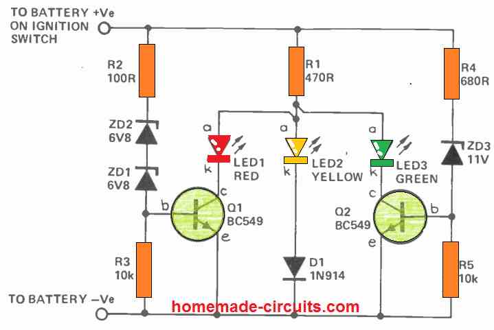
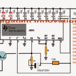
The proposed 3 LED battery level indicator can be typically used for monitoring a 12 V lead acid battery charge level, through 3 distinct LED illumination. The entire circuit is built using just a couple of BJTs , a few zener diodes, resistors and LEDs.
Different Ways to Check Battery Voltage
A hydrometer is perhaps the most efficient way to examine the condition of a lead acid battery. Hydrometers, on the other hand, have a variety of disadvantages. Because they're constructed of glass, they're delicate and can be dangerous to use while driving.
The tiny quantity of battery acid which persists on them poses a storage issue since the droplets and vapors corrode most metals and substances. These may be good for a garage, however justifying their cost for the rare usage in house workplaces is often not practical.
Measuring the voltage with load connected is yet another way to verify the battery's status. Under a typical functional load, a lead-acid car battery in an acceptable state of charge (Soc) will have a voltage level between 11.6 and 14.2 volts. When a battery's voltage level falls beneath 11.6 volts, its capacity is drastically reduced, and it discharges fast.
This situation might not allow to turn the starting motor for too long, most of the time! If the voltage on load, on the other hand, is more than 14.5 volts, the battery is completely charged!
If it stays in this condition for an extended period of time while the car is being driven, the alternator-regulator system may go faulty, and the battery could well be destroyed due to overcharging.
There are several methods for determining the battery voltage. A digital panel meter arranged as a voltmeter might be used. However, their disadvantage is that they are approximately 10 times more expensive than a hydrometer!
Using a 'expanded-scale voltmeter' is another best option.
A squint-and-peer practice is required to display the voltage range between 11 and 15 volts on a meter front, calibrated at 0-16 volts. It's even worse on a 0-30 volts scale, which is common on contemporary multimeters.
A meter that measures 11 volts at the lower end of the scale and 16 volts at the extreme end of the scale works perfect. As a result, the phrase 'extended-scale' is coined.
However, you wouldn't want to be staring at a meter on the dashboard while driving in traffic. The voltage range in which your battery is most effective is just about 2 volts.
What is actually required is an indication that only takes a passing glance and does not require any 'analysis.' That's precisely what we've tried to accomplish in this project.
Making a 3 LED Indicator
We created a simple 3 LED battery indicator circuit that displays the following:
- Yellow indicates that the battery is 'low'.
- Green indicates that the battery is in good condition.
- Red indicates that the battery has been overcharged.
A yellow indicator illuminates when the battery voltage falls below 11.6 volts. This implies that the battery is either undercharged or that a large load (such as high-powered driving lights) is draining too much power.
When the voltage is between 11.7 and 14.2 volts, the green LED light turns on, indicating that everything is well.
When the red indicator illuminates, which it would if the voltage exceeds 14.2 volts, the vehicle's voltage regulator may need to be adjusted, or there may be another issue.
Circuit Description
The working of this 3 LED battery indicator circuit is dependent on the varying voltage drops across the different color LEDs.
The voltage drops across red, yellow, and green LEDs at 20 mA are generally 1.7V, 3.0V, and 2.3 volts. Q1 and Q2 are turned off by R3 and R5 when the vehicle battery voltage becomes extremely low for either ZD1/ZD2 or ZD3 to conduct.
The yellow LED is forward biased and conducts through D1 under these conditions, generating a voltage of roughly 3.7 volts at point A. (see circuit diagram). ZD3 starts conducting as soon as the supply voltage increases over 11.6 volts, biasing Q2 on. The green LED illuminates due to its low forward voltage specs, lowering the voltage at point A to around 2.6 volts.
Because this isn't enough to turn on D1/LED3, the yellow LED turns off. The yellow LED's bias is 'stolen' by the green LED.
Q1 is biased on when the supply voltage exceeds 14.2 volts, and the red LED 'robs' the bias from the green LED. The red LED alone conducts when the voltage at point A drops to two volts.
The current via the LEDs is limited by R1. The Q1 base currents are limited by R2 and R4.
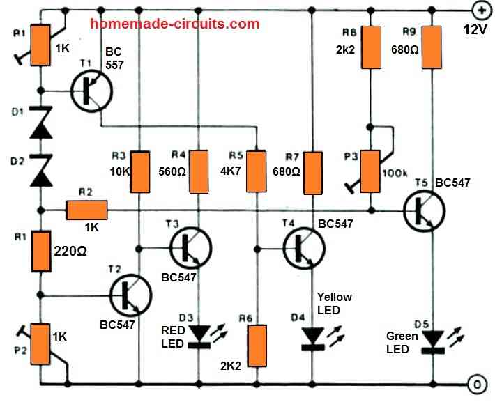
Another Simple Design
Just three LEDs are utilized to indicate the battery state of the automobile (or boat). The LEDs are lit in the following manner:
D3 – 12 volts
12…13 V = D3 + D4
D4 = 13…14V
D4 + D5 > 14 V
Preset P2 determines the voltage at which D3 turns off (13 V); PI determines the voltage at which D4 turns on (12 V); and P1 determines the voltage at which D5 turns on (13 V) (14 V).
Because the different changes influence each other, the setting up procedure is very important and will need to be done multiple times. The author's prototype is shown in the image.

Comments
Hello Sir
I would like to ask a question. it is about designing a test equipment. There is a circuit board that needs to be tested. The board consume 24VDC and 6A ( short time)supply current and voltage . There must be two indicators as well as LEDs, one green and other red, if it has fault on the board, it should be flashing red leds. if it has no fault, then it will display normal green led. If you can share any idea with me , it would be great .
Thanks for your understanding
Hello Abhishek, how do we know there’s a fault in the board?
thank you very much for your reply
the board is already installed. at the output it is connected to the fan(24V/DC) and a heater(short time 2 to 6A). If the fan and heater doesn’t work, there we have an error on the board. the probabilities error we have to build up by a circuit.If it sometimes occur on the board can be short circuit or contact between components feet. If everything works well (fan and heater), then green LED should be displayed. If there is an error (short circuit or overvoltage or undervoltage), then red LED should be displayed.
Thank you for urs Understanding
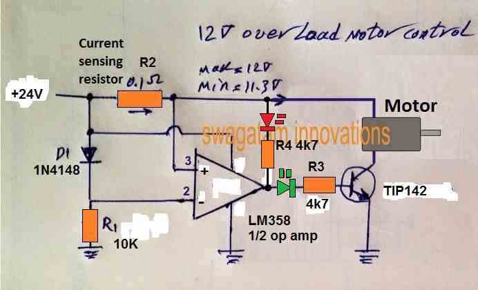
The over voltage indicator may not be required, because when an over over voltage happens the motor will start drawing more current and the situation will convert into an over current or over load. But this circuit will not show an under voltage, for that you may have to employ another op amp.
The circuit has a transistor to control the over current situation for the motor. If you don’t want this feature, you can remove the transistor and connect the green LED 4k7 with the ground line.
Here’s a simple current controller which you can modify according to your needs:
Hi Swagatam,
I’ve been struggling with a small problem which seems to me should be simple but apparently isn’t.
I have an old R/C transmitter (Circa early ’80s) that has an analog meter on it. I’ve learned that it takes about 3V to get full scale deflection, and that the internal resistance is about 2.8k. I am using a LiFeP04 two cell battery to power the transmitter, which gives about 7.2V on a full charge, but is basically flat at about 5.6V. I would like to hook up the meter to the battery so that it will read full deflection when the battery is at 7.2V and zero at around 5.6V. The voltages aren’t set in stone but I’d like something vaguely close. It doesn’t need to be super accurate, it just needs to give me an indication if it’s safe to fly or not. I guess anything less than about half (or maybe a third) would be a hint that it might be advisable to pack up and go home.
I know nearly nothing about electronics, so I’m really just looking for a recipe I can follow to hook it up.
All advice gratefully received.
😉 Ian
PS apologies if this query is too far off topic for this article. It was the closest I could find.
Hi Ian,
you can reduce the sensitivity of the 3 V FSD meter by connecting a shunt resistor across its terminals. You can apply 7.2V and experiment by connecting different value resistors parallel to the meter terminals until the meter needle just settles at the full scale deflection.
You can try resistors between 0.1 ohm to 1 ohm and check which resistor actually fulfills the requirement.
Hi Swagatam and thanks for you quick reply. I’ll try your suggestion.
😉 Ian
Hi Ian, I am sorry, the above suggestion is actually suitable for stepping down current, not voltage. For stepping down voltage you will need to attach a voltage divider with your meter as demonstrated in the following diagram: