• Skip to main content
  • Skip to primary sidebar

Homemade Circuit Projects

Need circuit help? Post them in the comments! I've answered over 50,000!

Blog | Categories | About | Contact | Calculators-online
You are here: Home / Datasheets and Components / 2N3906 Datasheet [40V, 200 mA, PNP Transistor]

2N3906 Datasheet [40V, 200 mA, PNP Transistor]

Last Updated on January 19, 2025 by Swagatam Leave a Comment

In this post I have explained the complete datasheet of the transistor 2N3906. It is the complementary to the transistor 2N3904. Here is the complete datasheet for the 2N3906 PNP transistor.

Table of Contents
  • Pinout Configuration
  • Absolute Maximum Ratings:
  • Electrical Characteristics:

Pinout Configuration

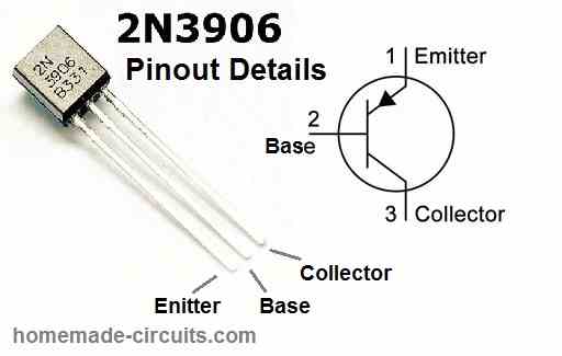
The transistor 2N3906 has 3 pinouts named as emitter, base and collector. These pinouts are arranged as shown in the following figure:

2N3906 pinout details

Absolute Maximum Ratings:

The negative signs indicate that it is a PNP transistor.

  • Collector-Emitter Voltage: -40 V
  • Collector-Base Voltage: -40 V
  • Emitter-Base Voltage: -5 V
  • Collector Current: -200 mA
  • Total Power Dissipation: 625 mW
  • Operating Junction Temperature: -55 to 150 °C
  • Storage Temperature: -55 to 150 °C

Electrical Characteristics:

  • Collector-Emitter Breakdown Voltage (IC = -1 mA, IB = 0): -40 V
  • Collector-Emitter Saturation Voltage (IC = -10 mA, IB = -1 mA): -0.2 V
  • Base-Emitter Saturation Voltage (IC = -10 mA, IB = -1 mA): -0.65 V
  • DC Current Gain (IC = -1 mA, VCE = -10 V): 100 to 300
  • Maximum Collector Current (DC) (VCE = -1 V, IB = 0): -200 mA
  • Transition Frequency (IC = -10 mA, VCE = -20 V, f = 100 MHz): 250 MHz
  • Input Capacitance (VBE = -5 V, IC = 0, f = 1 MHz): 8 pF
  • Output Capacitance (VCE = -10 V, IC = 0, f = 1 MHz): 4 pF
  • Reverse Transfer Capacitance (VCE = -10 V, IC = 0, f = 1 MHz): 1.2 pF

You'll also like:

  • 1.  Types of Inductors Explored
  • 2.  LM324 Quick Datasheet and Application Circuits
  • 3.  IC 4047 Datasheet, Pinouts, Application Notes
  • 4.  How to Understand and Use white LEDs – Datasheet
  • 5.  EGS002 Datasheet, Circuit Diagram Explained
  • 6.  High Current Zener Diode Datasheet, Application Circuit

Filed Under: Datasheets and Components Tagged With: 200, 2N3906, 40V, Datasheet, PNP, Transistor

About Swagatam

I am an electronics engineer and doing practical hands-on work from more than 15 years now. Building real circuits, testing them and also making PCB layouts by myself. I really love doing all these things like inventing something new, designing electronics and also helping other people like hobby guys who want to make their own cool circuits at home.

And that is the main reason why I started this website homemade-circuits.com, to share different types of circuit ideas..

If you are having any kind of doubt or question related to circuits then just write down your question in the comment box below, I am like always checking, so I guarantee I will reply you for sure!

Previous Post: « BC547 Transistor Datasheet [45V, 100mA NPN Transistor]
Next Post: Tracking Transmitter Circuit »

Reader Interactions

Need Help? Please Leave a Comment! We value your input—Kindly keep it relevant to the above topic! Cancel reply

Your email address will not be published. Required fields are marked *

Primary Sidebar


Subscribe to New Posts

Categories

  • Arduino Projects (88)
  • Audio and Amplifier Projects (132)
  • Automation Projects (17)
  • Automobile Electronics (101)
  • Battery Charger Circuits (83)
  • Datasheets and Components (104)
  • Electronics Theory (143)
  • Free Energy (37)
  • Games and Sports Projects (11)
  • Grid and 3-Phase (19)
  • Health related Projects (25)
  • Home Electrical Circuits (12)
  • Indicator Circuits (14)
  • Inverter Circuits (88)
  • Lamps and Lights (142)
  • Meters and Testers (69)
  • Mini Projects (46)
  • Motor Controller (64)
  • Oscillator Circuits (27)
  • Pets and Pests (15)
  • Power Supply Circuits (108)
  • Remote Control Circuits (50)
  • Security and Alarm (64)
  • Sensors and Detectors (101)
  • Solar Controller Circuits (59)
  • Temperature Controllers (42)
  • Timer and Delay Relay (49)
  • Transmitter Circuits (29)
  • Voltage Control and Protection (37)
  • Water Controller (36)

Tags

Alarm Amplifier Application Arduino Automatic Battery Charger Circuits Control Controlled Controller Current Datasheet DC Detector Digital Driver Electronic Explained Explored Generator High Indicator Inverter Lamp LED Light Meter Motor Pinout Power Regulator Remote Sensor Simple Single Solar Supply Switch Timer Transistor Voltage Water Watt Working


Other Links

  • Privacy Policy
  • Cookie Policy
  • Disclaimer
  • Copyright
  • Videos
  • Sitemap


People also Search

555 Circuits | 741 Circuits | LM324 Circuits | LM338 Circuits | 4017 Circuits | Ultrasonic Projects | SMPS Projects | Christmas Projects | MOSFETs | Radio Circuits | Laser Circuits | PIR Projects |

Social Profiles

  • Twitter
  • YouTube
  • Instagram
  • Pinterest
  • My Facebook-Page
  • Quora
  • Stack Exchange
  • Linkedin


  • Recent Comments

    • Swagatam on 7 Modified Sine Wave Inverter Circuits Explored – 100W to 3kVA
    • Victor on 7 Modified Sine Wave Inverter Circuits Explored – 100W to 3kVA
    • Victor on 7 Modified Sine Wave Inverter Circuits Explored – 100W to 3kVA
    • Swagatam on How to Calculate Ferrite Core Transformers
    • Swagatam on Over Current Cut-off Power Supply Using Arduino

    © 2025 · Swagatam Innovations