In this article we will try to understand how to build a 220V AC to 48 V DC SMPS circuit for charging all types of 48V batteries, using the nice little IC IR2153. However, since 48V battery will require a 56V DC, so we will rather discuss a 220V to 56 V DC battery charger circuit SMPS circuit, in this post.
Why 48 V Battery needs around 56 V DC For Proper Charging
Now we have to understand an important point about the purpose of this 56 V SMPS, because even though we call the battery a 48 V battery, it will never get fully charged at 48 V.
Therefore we always need a higher charging voltage so that the charging current can actually enter the battery plates.
When you look at any 48 V battery system whether it is a lead acid type or any other chemistry that works around similar voltages, then you will see that the full-charge voltage always goes above the nominal battery voltage.
So when we take the example of a standard 48 V lead acid battery which internally has four 12 V sections, then each 12 V section needs around 14 V for proper full-charge top-up.
When we multiply 14 V * 4 then we get 56 V which becomes the correct charging voltage for the whole 48 V battery bank.
This 56 V ensures that the electrolyte inside the battery reaches full chemical saturation and it also ensures that the battery reaches 100 percent state-of-charge without remaining undercharged.
And when we talk about SMPS charging, we always need to give a clean and stable DC to the battery, because any ripple or drop reduces the effective charging voltage.
So the SMPS must supply a little above 56 V when lightly loaded so that after filtering and load adjustments it settles close to 56 V under charging current.
This is why we designed the secondary of the ferrite transformer to give around 40.6 V RMS which becomes around 56 V DC after rectification and filtering and that becomes the exact voltage which a 48 V battery needs for full charging.
Now we also have to remember that when you want to limit the charging current for the battery then you must introduce either a current control loop or a series regulating stage.
This is because even though the SMPS gives 56 V smoothly, still the battery will draw very high current when the battery is discharged heavily and that can stress the SMPS components, so the current limiting stage becomes an important requirement.
So even though the battery is called a 48 V battery still the correct charging voltage always becomes around 56 V because only then the battery can reach its full capacity, and only then the SMPS can deliver proper charging behavior without leaving the battery half charged.
Working Of The Input Section
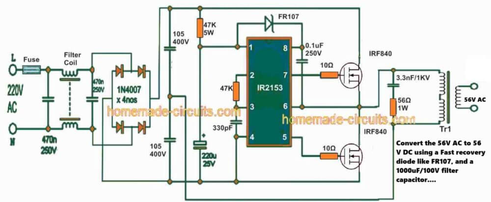
When we connect the 220 V AC mains to this circuit then the current first passes through a fuse and an EMI filter coil along with a couple of 470 nF capacitors, and this EMI filter stage helps in removing the unwanted noise, spikes, and disturbances.
Because of this the corresponding SMPS circuit stage receives a cleaner AC supply and when this cleaned AC reaches the 1N4007 diode bridge then it gets rectified into high voltage DC which becomes around 310 V, because 220 V AC RMS becomes around 311 V peak and this high voltage DC is stored inside the two main 105, 400 V capacitors.
Circuit Diagram
Powering The IR2153
The IR2153 IC needs a small amount of current so that it can start oscillating, and this small current comes from the 47 K 5 W resistor and the FR107 diode.
Now the IC charges its internal supply capacitor slowly so that there is no sudden inrush, and when the voltage inside the IC becomes sufficient then it begins to work and it starts producing the gate drive signals for the two IRF840 MOSFETs.
Oscillator Frequency
The IR2153 uses a simple timing network made of 47 K and 330 pF to set its switching frequency and with these values the frequency becomes near 44 kHz.
Since this IC already contains the half-bridge driver inside it, so we do not need any extra driver circuit for the MOSFETs and the IC automatically provides alternate gate pulses with a built-in dead time so that the MOSFETs do not conduct together.
Half Bridge Switching
The two IRF840 MOSFETs form a half-bridge configuration where one MOSFET remains on the upper side of the DC bus.
The other MOSFET remains on the lower side and the center point between these MOSFETs becomes the switching node.
This switching node gets connected to the primary of the ferrite transformer so that the transformer sees a square wave voltage and since this is a half-bridge design, so the transformer primary receives only half of the total DC bus.
Meaning around 155 V peak instead of 310 V, and this alternating 155 V square wave continuously reverses the magnetic flux inside the ferrite core.
Snubbers And Gate Resistors
We can see a 3.3 nF / 1 kV capacitor and a 56 Ω resistor on the transformer secondary which act like a snubber network so that the high frequency ringing is controlled.
Also the 10 Ω resistors on the MOSFET gates help in controlling the gate transition speed so that the MOSFETs remain stable and free from unnecessary oscillations.
Designing The Transformer For 56 V DC Output
Here we first calculate how much secondary RMS voltage we need when we want around 56 V DC after rectification.
Since the final DC output is nearly equal to Vpeak minus the diode drops, we add the diode drop of around 1.4 V to 56 V and get around 57.4 V peak and when we convert this into RMS by dividing by 1.414 then we get around 40.6 V RMS, so the transformer secondary must produce around 40.6 V RMS.
Turns Per Volt Calculation
Ferrite transformers working at high frequency use the formula:
N = V / (4 * f * Bmax × Ac)
We normally convert this into turns per volt:
N/V = 1 / (4 * f * Bmax × Ac)
Here:
f ≈ 44 kHz
Bmax ≈ 0.20 Tesla (safe value to avoid saturation)
Ac ≈ 100 mm² (example core cross-section) = 1 * 10⁻⁴ m²
Let us now put these values:
N/V = 1 / (4 * 44373 * 0.20 * 1×10⁻⁴)
N/V ≈ 0.2817 turns per volt
Primary Turns Calculation
The half-bridge voltage on the transformer primary is around 155 V peak, so:
Np = 155 * 0.2817 ≈ 43.7 turns
We round this to 44 turns.
Secondary Turns Calculation
Secondary requirement = 40.6 V RMS.
Ns = 40.6 * 0.2817 ≈ 11.44 turns
We round to 12 turns.
This 12 turn winding will give around 56 V DC after the rectifier and the capacitor, and small adjustments can be done by adding or removing one or two turns depending on load behavior.
Considerations About Core Size, Wire Gauge, And Skin Effect
When the core area is smaller than 100 mm² then the turns per volt increase because the core saturates faster but when the core is larger than 100 mm² then the turns per volt decrease.
Hence we must always adjust the calculation depending on the actual core size and since the operating frequency is above 40 kHz, so the skin effect becomes noticeable.
So we should use multiple thin strands for both primary and secondary instead of a single thick wire so that we reduce copper losses and heating.
Calculator Tool
You can also consider using this SMPS calculator tool verifying the results of the ferrite transformer turns and winding ratios.
Conclusion
This is how the complete IR2153 SMPS circuit works from the input rectification stage up to the half-bridge switching and transformer operation, and this is also how we can calculate the primary and secondary turns so that the SMPS can generate around 56 V DC from a 220 V AC input.
When you provide the exact ferrite core type such as EE42, EE55, ETD39, or ETD44 then the transformer can be recalculated perfectly for that specific core.