In this post I will show how to construct a circuit which can detect color and trigger respective assigned relays. This project is accomplished using TCS3200 color sensor and Arduino board.
Color Sensing by TCS3200
If you haven’t read the previous article, please go through it where we have discussed the basics of color sensing using TCS3200
The proposed project may be useful, if you want a circuit to take action based on colors. There are oceans of applications based on color detection in various industrial fields.
This project will give an insight on how we can program the color sensor to detect different colors and trigger the relays.
We are going to consider the primary colors: RED, GREEN and BLUE for this project. This project can differentiate between these three colors and trigger the relays, each relay for each color.
The TCS3200 can detect any number of colors, but to keep the project understandable and to keep program code simple, we are concentrating only on the primary colors.
Circuit Diagram:
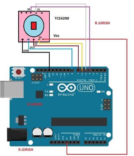
The above schematic is for interfacing the Arduino and TCS3200 colour sensor.
Relay connections:
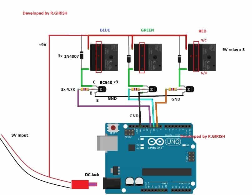
Power the Arduino with 9V adapter with at least 500mA. The transistor acts as amplifier for relay since the Arduino’s GPIO pins cannot provide sufficient current to relay.
The diode 1N4007 will absorb high voltage spikes from relay coil, protecting rest of the semiconductor components.
That concludes the hardware.
Now let’s see how to upload the code and calibrate the sensor for your requirements.
The color sensitivity can vary from module to module and ambient light can alter the color sensitivity drastically.
All the TCS3200 sensors have some variation while fabricating, you have to measure the color parameters for the sensor which you currently own, so that those parameters can be used in the code to detect the color more accurately.
To calibrate and optimize the readings for your sensor follow, the steps precisely:
Step 1: Upload the following code with completed hardware setup.
//--------Program Developed by R.GIRISH-------//
const int s0 = 4;
const int s1 = 5;
const int s2 = 6;
const int s3 = 7;
const int out = 8;
int frequency1 = 0;
int frequency2 = 0;
int frequency3 = 0;
int state = LOW;
int state1 = LOW;
int state2 = HIGH;
void setup()
{
Serial.begin(9600);
pinMode(s0, OUTPUT);
pinMode(s1, OUTPUT);
pinMode(s2, OUTPUT);
pinMode(s3, OUTPUT);
pinMode(out, INPUT);
//----Scaling Frequency 20%-----//
digitalWrite(s0, state2);
digitalWrite(s1, state1);
//-----------------------------//
}
void loop()
{
//-----Sensing RED colour-----//
digitalWrite(s2, state1);
digitalWrite(s3, state1);
frequency1 = pulseIn(out, state);
Serial.print("RED = ");
Serial.print(frequency1);
Serial.print(" |");
delay(100);
//------Sensing Green colour----//
digitalWrite(s2, state2);
digitalWrite(s3, state2);
frequency2 = pulseIn(out, state);
Serial.print(" Green = ");
Serial.print(frequency2);
Serial.print(" |");
delay(100);
//------Sensing Blue colour----//
digitalWrite(s2, state1);
digitalWrite(s3, state2);
frequency3 = pulseIn(out, state);
Serial.print(" Blue = ");
Serial.println(frequency3);
delay(100);
Serial.println("-----------------------------");
delay(400);
}
//---------Program Developed by R.GIRISH---------//
Step 2: Open the serial monitor, you will find the color parameters like this:
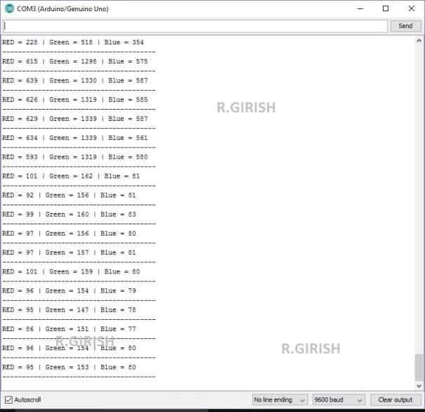
Bring the color object (colored paper is preferred) red, blue and green.
Step 3:
• Place the red colored paper close to the TCS3200 sensor.
• Note down the R, G, B readings (all three colours) while you place the red colour paper.
• Similarly note down the R, G, B reading for green and blue color papers.
• NOTE: when you place any of the 3 colors in front of the TCS3200 note down all the red, blue and green readings for each color paper, which you need to enter in the main color detection program.
Step 4: Read Step 5 and upload the main below code (color detection program)
//-----Program Developed by R.GIRISH-----//

const int Red_relay = 9;
const int Green_relay = 10;
const int Blue_relay = 11;

const int s0 = 4;
const int s1 = 5;
const int s2 = 6;
const int s3 = 7;
const int out = 8;

int var = 25;

int red = 0;
int green = 0;
int blue = 0;

int state = LOW;
int state1 = LOW;
int state2 = HIGH;

//-----------Enter Values--------//
//For RED Colour:
int Rx1 = 92;
int Gx1 = 240;
int Bx1 = 53;

//For GREEN Colour:
int Rx2 = 228;
int Gx2 = 163;
int Bx2 = 64;

//For BLUE Colour:
int Rx3 = 300;
int Gx3 = 144;
int Bx3 = 45;
//----------------------------//

void setup() {

  Serial.begin(9600);

  pinMode(Red_relay, OUTPUT);
  pinMode(Green_relay, OUTPUT);
  pinMode(Blue_relay, OUTPUT);

  digitalWrite(Red_relay, LOW);
  digitalWrite(Green_relay, LOW);
  digitalWrite(Blue_relay, LOW);

  pinMode(s0, OUTPUT);
  pinMode(s1, OUTPUT);
  pinMode(s2, OUTPUT);
  pinMode(s3, OUTPUT);
  pinMode(out, INPUT);

  // Scaling Frequency 20%
  digitalWrite(s0, state2);
  digitalWrite(s1, state1);
}


void loop() {

  // Turn off all relays before every detection cycle
  digitalWrite(Red_relay, LOW);
  digitalWrite(Green_relay, LOW);
  digitalWrite(Blue_relay, LOW);

  // Calculate detection windows
  int redH1 = Rx1 + var;
  int redL1 = Rx1 - var;
  int redH2 = Rx2 + var;
  int redL2 = Rx2 - var;
  int redH3 = Rx3 + var;
  int redL3 = Rx3 - var;

  int greenH1 = Gx1 + var;
  int greenL1 = Gx1 - var;
  int greenH2 = Gx2 + var;
  int greenL2 = Gx2 - var;
  int greenH3 = Gx3 + var;
  int greenL3 = Gx3 - var;

  int blueH1 = Bx1 + var;
  int blueL1 = Bx1 - var;
  int blueH2 = Bx2 + var;
  int blueL2 = Bx2 - var;
  int blueH3 = Bx3 + var;
  int blueL3 = Bx3 - var;

  //-----Sensing RED Colour-----//
  digitalWrite(s2, state1);
  digitalWrite(s3, state1);
  red = pulseIn(out, state, 100000);
  delay(100);

  //-----Sensing GREEN Colour-----//
  digitalWrite(s2, state2);
  digitalWrite(s3, state2);
  green = pulseIn(out, state, 100000);
  delay(100);

  //-----Sensing BLUE Colour-----//
  digitalWrite(s2, state1);
  digitalWrite(s3, state2);
  blue = pulseIn(out, state, 100000);
  delay(400);


  //-----Match for RED-----//
  if (red <= redH1 && red >= redL1 &&
      green <= greenH1 && green >= greenL1 &&
      blue <= blueH1 && blue >= blueL1)
  {
    Serial.println("Detected Colour: RED");
    digitalWrite(Red_relay, HIGH);
    delay(1000);
    return;
  }

  //-----Match for GREEN-----//
  if (red <= redH2 && red >= redL2 &&
      green <= greenH2 && green >= greenL2 &&
      blue <= blueH2 && blue >= blueL2)
  {
    Serial.println("Detected Colour: Green");
    digitalWrite(Green_relay, HIGH);
    delay(1000);
    return;
  }

  //-----Match for BLUE-----//
  if (red <= redH3 && red >= redL3 &&
      green <= greenH3 && green >= greenL3 &&
      blue <= blueH3 && blue >= blueL3)
  {
    Serial.println("Detected Colour: Blue");
    digitalWrite(Blue_relay, HIGH);
    delay(1000);
    return;
  }

  // If no match
  Serial.println("Unknown Colour");
}
Step 5: In the above code replace the values with your values which you noted down recently:
Now we come to Step 5 and here we explain step by step way. We know that every sensor gives different R G B numbers, so we must put our own values inside the code.
So now we tell you how to do that. When you keep the red paper on the sensor, then you will see three numbers on the serial monitor, and these three numbers will look something like R = 56, G = 78, B = 38.
We take these three values as the real reading of your red colour under your light condition. So we take these three numbers and we replace the default numbers inside the code.
So now we go to the part of the code where it says For RED Colour, and we put the numbers like this:
For RED Colour:
int Rx1 = 56;
int Gx1 = 78;
int Bx1 = 38;
Now you do the same thing for the green paper and the blue paper. When you place the green paper then you will get one R value, one G value and one B value and then you put those three numbers under the For GREEN Colour lines.
When you place the blue paper then you will get the next three values and then you put them under For BLUE Colour lines.
So once you finish putting your own three sets of R G B values, then you upload the code again. Now the code will correctly detect your three colours because we have given the real readings to the program, and it will match those readings when you place any colour in front of the sensor.
Entering The Calibration Values In The Code
Now we talk about that part inside the code where we have written the default values for RED, GREEN and BLUE colours. We keep this part in the code because we want you to see clearly where you must change the numbers with your own readings. So you will see something like this in your program:
//------ Enter Values ------//
//For RED Colour:
int Rx1 = 92;
int Gx1 = 240;
int Bx1 = 53;

//For GREEN Colour:
int Rx2 = 228;
int Gx2 = 163;
int Bx2 = 64;

//For BLUE Colour:
int Rx3 = 300;
int Gx3 = 144;
int Bx3 = 45;
//--------------------------//
So When you place your red paper on the sensor, then the serial monitor will show three numbers, for example R = 56, G = 78, B = 38. So now you take these three values and you replace the old numbers like this:
//For RED Colour:
int Rx1 = 56;
int Gx1 = 78;
int Bx1 = 38;
Now you do the same for the green paper and the blue paper. So when you put the green paper then you use those readings under the GREEN section. When you put the blue paper, then you use those readings under the BLUE section.
So after you finish replacing all three sets of values, then you upload the code again and the colour detector becomes fully calibrated.
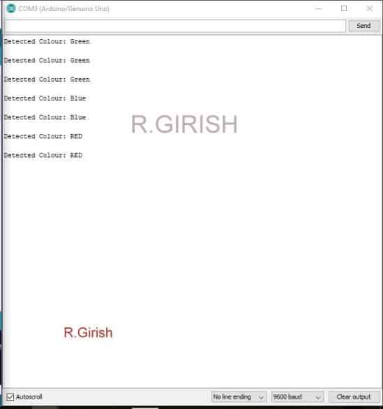
Step 6: Testing The Colour Detection
Now we test the circuit. So you open the serial monitor and you place any colour paper in front of the sensor. Then you will see the name of the detected colour on the serial monitor and at the same time the correct relay will turn ON.
• You have press reset button on Arduino board to deactivate the relay.
NOTE 1: The circuit may not detect the colors, if you place slightly different shade/tint of RED, GREEN, BLUE colored object/paper, after calibration. In other words, you have to use exactly same colored object/paper to detect colors and to trigger relay.
NOTE 2: Ambient light can affect the color detection so, please maintain a consistent light near the sensor while calibrating and also while detecting colors.
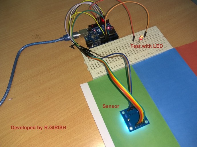
Author’s prototype:
If you have any questions regarding this project, please express in the comment section, you may receive a quick reply.


Need Help? Please Leave a Comment! We value your input—Kindly keep it relevant to the above topic!