This little transmitter will allow you to communicate, chat, send music transmission on any standard FM Radio tuned within the existing band, across a radial distance of not less than 500 meters or half a kilometers.
Warning: Using this transmitter could be illegal in your country or area, take appropriate permissions before indulging.
How it Works
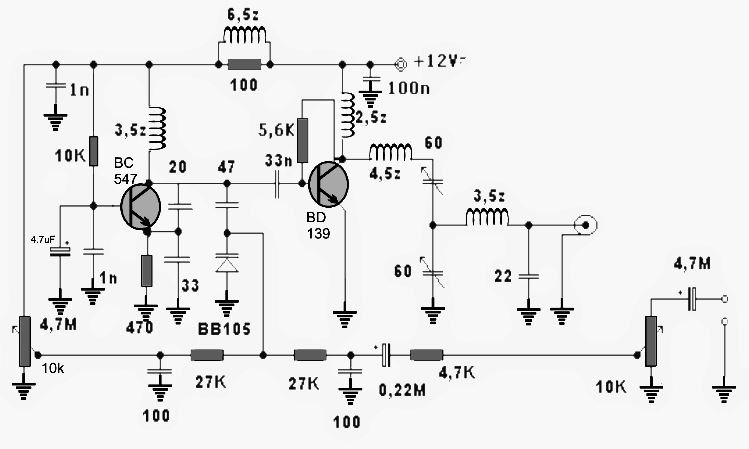
The circuit of this 1.5 watt transmitter is fundamentally configured for driving a tuned RF amplifier stage by an oscillator stage.
Referring to the diagram we find that the BC547 is rigged in a oscillator mode which resembles a Pierce oscillator circuit.
The base of the BC547 is biased by the 10k resistor, and the crucial RF coil is connected across the collector/positive of the transistor.
As soon as power is switched ON, this coil is resonated by the 20pF capacitor across the transistor collector and emitter.
The 33pF capacitor makes sure that the capacitance does not exceed the maximum specs of the design.
The above capacitor also determines and fixes the working band frequency of the circuit which is within 80 MHz and 110 MHz.
The varicap diode is included in order to convert the fed input voice or music signal into riding electrical pulses over the carrier frequency created by the above discussed oscillator stage.
This modulated signal is fed to the base of the amplifier stage consisting of the BD139 transistor via a bocking 33nF capacitor.
The BD139 picks up the signals and matches it up with the tuned network across its collector terminals formed by the two inductors and a couple of capacitive trimmers.
These trimmers must be adjusted precisely so that the input modulated signal is optimally amplified by this stage and results in a maximum transmission output.
The output is terminated through another inductor which removes unwanted harmonics and feeds a clean amplified RF modulated signal over the connected antenna.
Antenna Specifications
The antenna should be a Yagi antenna as used for old TV sets.
The circuit must be attached very close to the antenna, preferably directly with the connecting points of the antenna.
The power supply can be fed from an external source, or a battery may be used for the same.
All the "earth" symbols must be joined together and terminated over a large copper base positioned right under the PCB...this need be done if a designed PCB is not used.
With a well designed PCB, the "earth" points must be terminated with the inbound large copper tracks which should cover the entire area of the PCB running beside the connecting tracks all across the board.
How to Set the presets
The two 10k pot may be used for optimizing the signal strength or the volume of the fed signal which is to be transmitted.
The BD139 will require a large heatsink attached with its tab.
How to Build the Coils
The term "z" associated with the coils refer to the "turns" or number of turns. For example 3,5z refers to 3.5 turns, 2,5z denotes 2.5 turns and so on.
All the coils for this 1.5 watt transmitter circuit use 0.6 mm super enameled copper wire wound over an air core having a diameter of 5 mm.


Discussion & Solutions
Hello there ! Do you have any simple circuit Serial IR transmitter/receiver of RS232 signals ?
Thanks in advance.
Sorry, I don’t have it at this moment.
I would think that this 1.5 watt TX would not be stable. It could have the authorities knocking on the door as it drifts up the band.
It needs crystal control to keep it on frequency.
The Bd139 type transistor may run at the operating frequency and lots of others at the same time. there seems very little bandpass tuning. having to rely on the accuracy of hand wound coils with no tuning slugs.
Bd 139 my work fine on top band, but it would not be my choice above 30mhz
Thank you for your useful suggestions, appreciate it!
thanks dear 🙏
BD139 100 Mhz amplification?
could i get more power from either a 2n3866 as pa transistor or a pair of them in parallel with the pa supply voltage separated and taken up to a 24v or 30 v dc rail . heat sinks and 0.5 ohm resistors on the emitters of the paired 2n3866,s
I don’t think parallel output transistors can help to increase power…. without modifying other elements in the circuit
bd139 works very well on fm
switching frequency of BD139 is 250 MHz
you are right,found one on youtube…as far as i know..bd139 works at maximum 50 mhz,used in AF,shortwave transmitters and many more fields ,not for VHF, but i found a datasheet with 190 mhz transition frequency and another with 80 mhz TF(different companies).Can't find the frequency/gain chart.
yes, BD139 looks more suitable for audio amps not for VHF or UHF FM applications, thanks for updating the info.
BD139 wont work in VHF freqvency,it is not made for that,for vhf…2n3553,BFW16..17,2n3632…and many more but BD 139 is not suitable for FM transmitters
BD139 works well in vhf frequency. I made an oscillator with it (102MHz) and equally used it in vhf rf amplifier and it works. Pls. give it a try too.
That's correct!
The circuit is not mine, it was referred from some other site…however strangely the original author claims to have tested it practically and proves it with images and video.
wow ! on 88-100 MHz BD139 GIVING 1.5 WATT. Yarr take a hike. If it was 2n3866 we could have some power. de vu3inj
Hi Swagatam
Can you give some alternative for 1SS99 diode, and i need to add a buzzer instead of meter.
Everybody is moving to DTH unwillingly, Digitization. Analog/Cable-TV and terrestrial, will be completely terminated at the end of 2014, In my area analog signals switched off suddenly cause of govt orders.., there r some pirated signal providers, their license also cancelled soon, So circuits like these come in handy for normal people.
Hi Max,
yes you are right……… the world is advancing rapidly and so should we.
You can google "silicon mixer and detector diode datasheet" you will find a few of the equivalents matching 1SS99.
Hello Swagatam,
i need you to modify the satellite signal finder circuit, with easily available parts in india.
the basic idea is -the power from STB to LNB is fixed, when RF signal get maximum that extra power is used to drive a meter/Piezo buzzer, the buzzer sound vari accoring to available signal strength…. we can use the sound variations to pin-point the Location of satellite, I wish you to modify the circuit with op-amp 741/tba820/tda2822m like components, here is the circuit & video
macq.comuv.com/sat-meter.pdf
http://www.youtube.com/watch?v=Ohi4XEmYW5w
Hello Max,
The circuit shown in the pdf is quite straightforward and uses standard components which are crucially matched with the system parameters…..so I think it should not be modified in any manner.
The opamp TLC271 is not so difficult to obtain so it's not a problem….moreover a 741 will not work as optimally as a TLC271 would do, so I think everything's perfect in the design and must be followed as it's given.
I'll surely include and discuss the design concept in my blog soon…thanks:)