The post investigates a cheap Chinese made 12V, 1 amp MOSFET based smps circuit which can be modified into 24V 1 amp, or 12V 2 amp smps circuits also. The MOSFET used is STB9NK60Z which is a highly advanced, rugged 600V 7A device specially manufactured for high, unpredictable, voltage environment circuit applications.
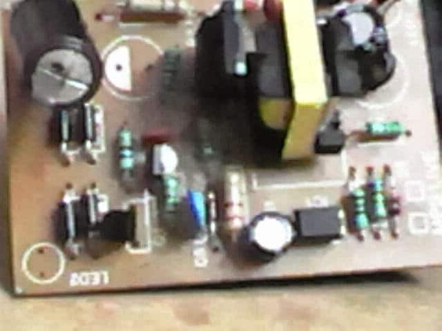
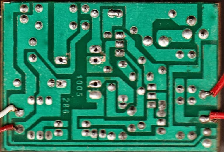
Reverse Engineering a 12V 1 Amp SMPS Adapter Physically
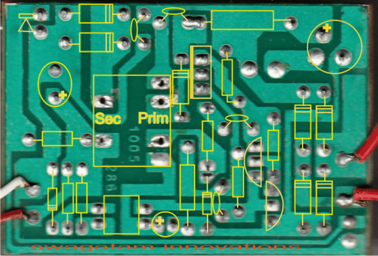
Coil Details:
The proposed 12V, 1 amp MOSFET based smps circuit utilizes a single E-core transformer, the winding details may be understood from the following info:
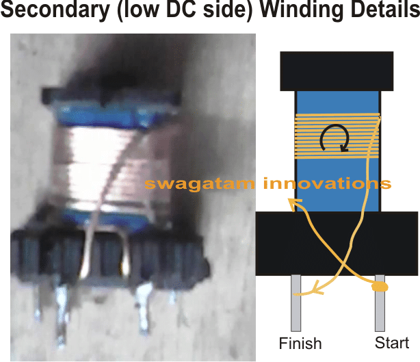
Wire thickness for the above secondary winding = 0.6mm, no. of turns = 12
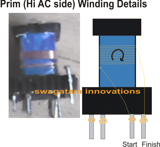
Wire thickness for the above primary winding = 0.25mm, no. of turns = 12
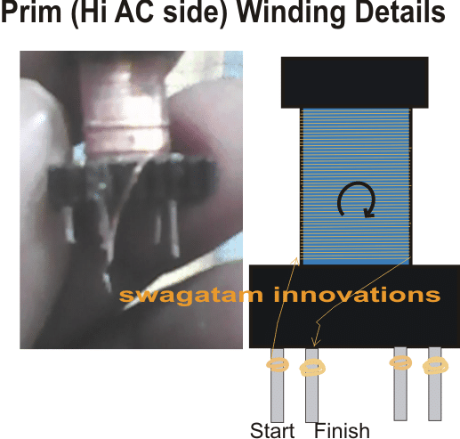
Wire thickness for the above primary winding = 0.25mm, no. of turns = 170
Feedback from one of the dedicated readers of this blog Mr. Debabrata Mandal:
I bought one today which is exactly the same, well, almost, cost me 100₹
Tested it @shop for 10 sec & it ran fine, brought home, plugged it in & was just about the test it with multimeter & there was a popping sound, though the indicator led was still glowing
Opened it and found that the electrolytic @ 12v side had blown, another 16v cap was burnt, in this condition I tested the output & found output at around 22-23v
Right now, I cannot check it properly because as soon as I turn it on, within a second the mosfet starts getting burning hot.
Also I can't figure out the transistors s9014 & s8550, what type or how their pins are configured?
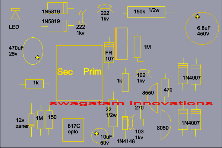
There are just 3 components different than the above design
100E/.5w instead of yr 150e/.5w (resistor)220e instead of your 270e (resistor) s9014 instead of your s8050 (transistor)
Without taking anything out of the board, I tested the diodes/zener, they looked fine to me.
So without taking out the transistor/mosfet could you tell me how to check them w/o having to turn the power ON... because that could melt the mosfet for sure.
Or whatever idea you can share to debug this... also, how do i tweak the circuit to 14v (13.6~14.4) & 1.1A (>1.05)
Possible Solution:
The mosfet should not become hot as long as the output is not loaded or short circuited.
If it's getting hot without any load at the output could mean a faulty primary section.
Confirm the status by doing the following steps:
Cut the PCB tracks of the secondary winding terminals such that it becomes completely isolated from the circuit board, confirm the continuity with a multimeter.
Next connect a 25 watt bulb in series with the input AC to the smps and switch ON power. If the 25 watt bulbs glows or if the mosfet shows significant heating would confirm a faulty primary stage.
The next step would be to remove the transistors one by one and replace them with new ones and apply the input voltage to check the mosfet condition.
If the heating persists then finally you can go for a mosfet replacement with a new one.After all these procedures are completed and the problem is fixed, we can go ahead to check why the secondary is generating a 24V output.
This could be due to a wrong winding data or may be once the primary stage is resolved as above, the output would also settle down with the correct output.
More Inputs from Mr. Debrata
OK I already took out the 2 transistors + mosfet + transformer and checked all looked fine, checked the resistors and capacitors, all seem to be fine and then I put them back & started checking the pcb itself...
I found a short, after soldering they didn't cut short that leg & it protruded & touched the copper film, so i cut it short & checked, now the output showed2.3v but still mosfet kept getting Hot.
Amazing... finally nothing to do, i replaced the blown cap with 1000u/16v keltron and what? The problem got fixed.
Analyzing the Issue
Wow that's indeed very interesting., so the problem was in the filter capacitor, once it got fixed, the opto-coupler could receive the feedback input from it and in turn helped to regulate the mosfet conduction.....
Anyway all's well that ends well.
Thanks for the feedback.


Comments
Please suggest me how can this circuit be used for 12v 2 amp dc output
use two wires simultaneously for winding the secondary turns.
How can this circuit be used for 12v 2 amp dc output
With ref to… https://www.homemade-circuits.com/2013/10/12v-24v-1-amp-mosfet-smps-circuit.html
I bought one today which is exactly the same, well, almost… cost me 100₹
Tested it @shop for 10sec & it ran fine… brought home, plugged in & was just bout the test with multi & there was a popping sound though the indicator led was still glowing
Opened & found that the electrolytic @ 12v side blew… a 16v cap blew… so i tested & found output as some 22-23v
Well i couldnt check properly cause as soon as am turning it on, in 1sec the mosfet is becoming burning hot
So…. help…. @my hobby days there was no smps so i donno how to fix them & its 100₹ non-refundable so i dont wanna throw it away
Also i donno bout the transistors s9014 & s8550… wat type or how their pins r arranged
Theres just 3components diff…
100e/.5w instead of yr 150e/.5w (resistor)
220e instead of yr 270e (resistor)
s9014 instead of yr s8050 (transistor)
Without taking anything out of the board, i tested the diodes/zener… they r fine it seems
So without taking out the transistor/mosfet if u could tell me how to check them w/o having to turn the power on… cause tat’ll melt the mosfet for sure
Or watever idea u can share to debug… also, how do i tweak the circuit to 14v (13.6~14.4) & 1.1A (>1.05)
I have updated the solution in the above post, please refer to it.
what is ur site address
thanks 🙂
Hi sir, I see you again on this SMPS project is a nice work but I don't understand the circuit diagram, so I need the schematic diagram of this project. Continue on your good doing God help you thanks.
If I get time I'll surley update the drawing here.
you can send it to homemadecircuits@gmail.com
Hi Swagatam sir, wishing you & ur family a very Happy Durga Puja…may Maa Durga fulfill all ur dreams…my best wishes r always with u…keep doing the good work sir…
Hi Sanatan,
Wish you all the very same!
God bless you!
Hey mr. swagatam love your work and designs. But could not find your contact details and email address on your site to contact to you about a project.
Hey Jaseem, see the left sidebar under Home, Privacy Policy…..you will find "contact" details also