A wireless mobile phone battery charger is a device that charges a compatible cellphone or mobile phone placed close to it, through high frequency wireless current transfer, without any physical contact.
In this post I have explained how to build a wireless cellphone battery charger circuit for facilitating a cordless cellphone charging without employing a conventional charger.
The Objective
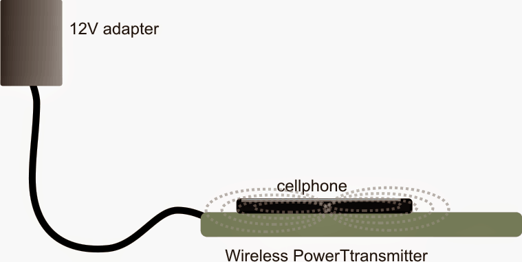
Here the cellphone is required to be installed with a receiver circuit module internally and connected to the charging socket pins, for implementing the wireless charging process.Once this is done, the cellphone simply needs to be kept over the wireless charger unit for initiating the proposed wireless charging.
In one of our earlier posts I have explained a similar concept which explained the charging of a Li-ion battery through a wireless mode, here too we employ a similar technique but try to implement the same without removing the battery from the cellphone.
Also, in our previous post I will comprehensively explained the basics of wireless charging, we'll take the help of the instructions presented there and try to design the proposed wireless cellphone charger circuit.
We'll begin with the power transmitter circuit which is the base unit and is supposed to be attached with the mains supply and for radiating the power to the cellphone module.
The Transmitter (Tx) Coil Specifications:
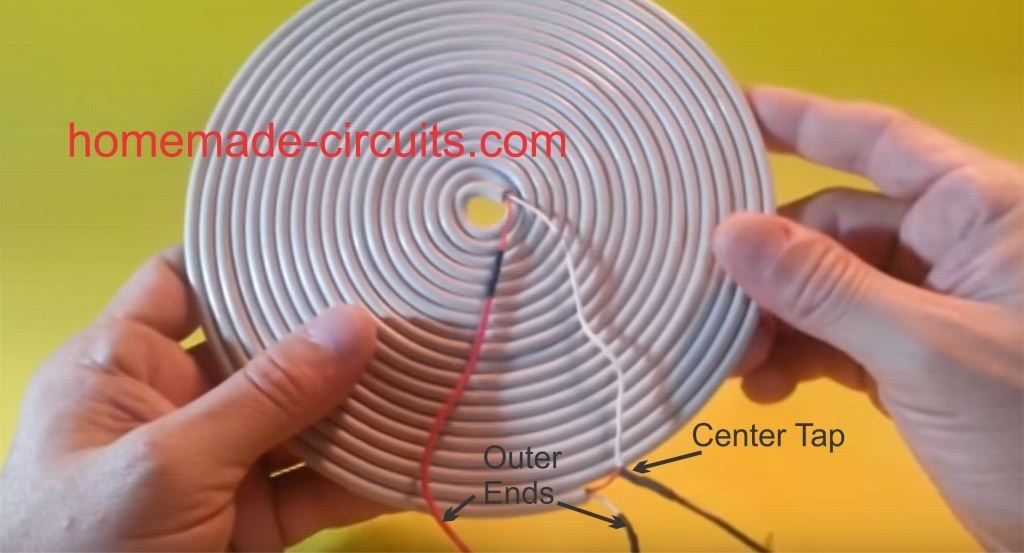
The transmitter circuit for this wireless cellphone battery charger is the crucial stage and must be built accurately, and it must be structured as per the popular Tesla's pancake coil arrangement as shown below:
Making a PCB version of the above Pancake coil.
Inspired from the above theory, the smaller layout of the same coil can be etched over a PCB as shown in the following diagram, and wired as indicated:
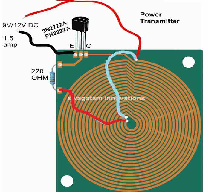
Dimensions: 10 inches by 10 inches, bigger size might enable faster charging and better current output
The figure above shows the power emitter or radiator design, also recall the circuit diagram from our previous post, the above design utilizes exactly the same circuit layout, although here we do it through a PCB by etching the winding layout over it.
A careful observation shows that the above layout has a pair of parallel coiled copper tracks running spirally, and forming the two halves of the transmitter coil, wherein the center tap is acquired with the aid of the linked red jumper wire across the ends of the coils.
The layout allows the design to be compact and effective for the required operations.
The track layout could be in the form of a square, or oval on one side and squarish on the other in order to make the unit even sleeker.
Rest of the portion is quite straightforward and is as per our earlier diagram, where the transistor is 2N2222 included for inducing the required high frequency oscillations and propagation.
The circuit is operated from a 12V/1.5 amp source, and the number of turns (coils) may selected approximately in accordance with the supply voltage value, that is around 15 to 20 turns for each halves of the transmitter coil. Higher turns will result in lower current and boosted voltage radiations and vice versa
When switched ON, the circuit may be expected to generate a strong magnetic flux around the coiled tracked, equivalent to the input power.
Now the radiated power needs to be absorbed using an identical circuit for executing the wireless power transfer and the intended cell phone charging.
For this we need a power collector or receiver circuit for collecting the radiated power, this may be devised as explained in the following section:
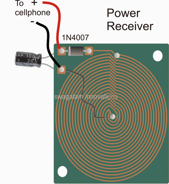
Dimension: 3 inches by 3 inches or as per the accommodation space available inside your cellphone
As may be witnessed in the above receiver design, an identical layout of the coil may seen, except that here the two concentric spirals are connected in parallel to add current in contrast to the transmitter layout which incorporated a series connection owing to the center tap restriction for the design.
The design is supposed to be small enough to fit inside a standard cellphone, just below the hind cover, and the output which is terminated through a diode may be connected either with the battery directly or across the charging socket pins (internally).
Once the above mobile battery charger circuits are built, the transmitter circuit may be connected with the indicated DC input, and the receiver module placed right over the transmitter board, at the center.
An LED with a 1k resistor could be included at the output of the receiver circuit in order to get a instant indication of the wireless power conduction process.
After the operation is confirmed, the output from the receiver may be connected to the socket of the cell phone for checking the response of the wireless charging effect.
However before this you may want to confirm the output to the cellphone from the wireless receiver module...it should be around 5 to 6V, if it's more, the black wire could be simply shifted and soldered a few coils towards the top until the right voltage is achieved.
Once all the confirmation are complete the module could be accommodated inside a cellphone and the connections done appropriately.
Finally, hopefully if everything is done correctly the assembly might allow you to keep the cellphone directly over the transmitter set up and enable the proposed wireless cellphone charging to happen successfully.
Making a Practical Prototype
The above wireless power transfer concept was successfully tried and tested with some modifications, by Mr. Narottam Gupta who is an an avid follower of this blog.
The modified wireless cellphone charger circuit diagram and the prototype images can be witnessed below:
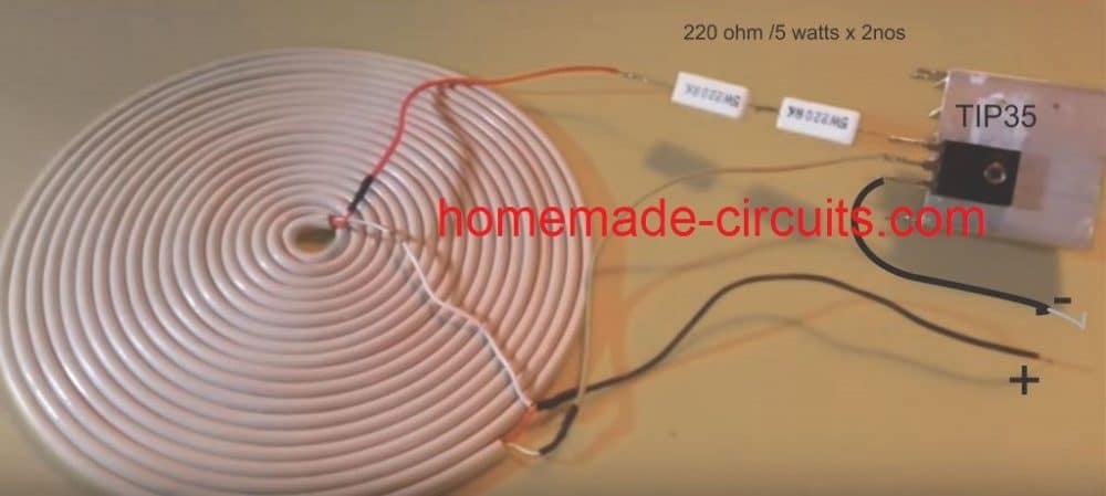
Detailed Working Description
We have got the transmitter coil which is designed as a center-tapped transformer. What this means is that there is a center tap that connects to the positive supply voltage which is at +12V. The two ends of the coil are then alternately switched to ground through the TIP35 transistor while we are running the circuit.
Transistor Switching
Now here is where it gets interesting with the TIP35. We have set it up as a self-oscillating transistor. This whole setup relies on feedback from one side of the coil back to the base of the transistor to keep those oscillations going strong. To get things started we have got a 330 Ω resistor connected to the base of the TIP35. This little guy provides the initial biasing needed to turn the transistor on just for a moment.
Induced Feedback
When current starts flowing through one half of our coil it creates a magnetic field in the transformer core. This magnetic field then induces a voltage in the other half of the coil which gives us that all-important feedback signal back to the TIP35's base. What is cool is that this feedback signal alternates in polarity which makes the transistor switch on and off.
Oscillation Formation
Thanks to this alternating feedback polarity our transistor keeps turning on and off repeatedly. This action creates oscillations in the coil and these oscillations generate an alternating magnetic field in our transmitter coil. This is what we use to wirelessly transfer power.
Role of the Center Tap
Now let us talk about that center tap again. It splits our transformer into two halves allowing the transistor to alternate current flow between them. This back-and-forth current flow is what actually generates those oscillations we have been talking about.
Main Features of the Oscillation
Finally let us touch on some key features of our oscillation. The frequency at which these oscillations occur is mainly determined by two things: the inductance of our coil and any stray capacitance present in the circuit. Since we are not using an explicit capacitor here we end up relying on:
The stray capacitance that exists between the coil windings.
The parasitic capacitance from the TIP35 transistor itself.
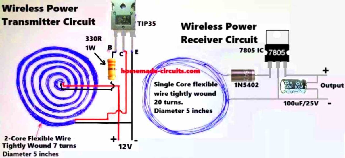
Prototype Description
We built this coil out of a flexible 2-core wire that is wound around 7 times and has a diameter of around 5 inches. This coil acts as the inductive element (L) in our LC circuit and its primary function is to generate an oscillating magnetic field at a specified frequency.
Next we have a 330-ohm resistor which restricts the base current flowing to the TIP35 transistor and also provides the necessary biasing conditions for it to function effectively.
The TIP35 is an NPN power transistor that can function as both a high-current switch and an oscillator. It is critical since it boosts the current required to drive that coil adequately.
The power supply outputs 12 volts of direct current which supplies the required input voltage to keep things working properly.
This is how the whole thing works. The circuit is a self-oscillating feedback loop. When we turn it on, the current flows into the TIP35's base via the 330 ohm resistor. A resonant LC circuit is made up of the coil, its inductance, and some parasitic or stray capacitance. The oscillation frequency is determined by the following formula:
f = 1 / (2 * π * √(L * C))where L is the inductance of the coil and C is that stray capacitance.
This resonant LC circuit produces oscillations at its natural frequency. The magnetic field formed by the current running through the coil produces an oscillating voltage which is supplied back to the TIP35's base to keep the oscillations continuing strong.
The TIP35 turns on and off fast sending high-frequency current through the coil. This action creates a strong oscillating magnetic field around the coil.
This pulsing magnetic field induces a voltage in a surrounding receiver coil using Faraday's law of electromagnetic induction. Essentially we are wirelessly transmitting energy from the transmitter coil to the receiver coil!
So why is this circuit oscillating? It all boils down to how the LC tank circuit (which consists of our transmitter coil and capacitance) interacts with the TIP35 transistor. The transistor amplifies the oscillations and then through our feedback loop the generated voltage in the coil reinforces the transistor's switching activity keeping those oscillations going.
The frequency at which our transmitter runs is determined by both the coil's inductance (L) and stray capacitance. If we know these numbers we can use our prior calculation to get the frequency.
Note:
It's worth noting that this circuit doesn't employ a dedicated capacitor, instead relying on stray capacitance from the coil and the wires. This can make our frequency more varied.
The TIP35 is designed to handle high power ensuring that there is enough current to create the required strong magnetic field.
If we wish to fine-tune the circuit we may do so by varying the inductance of the coil—by changing the number of turns or the spacing between them. This could help us create resonance with the receiver coil, resulting in optimal efficiency.
Formulas and Calculations
Transmitter Coil Design
Inductance (L) of the Coil:
L = (N2 * mu0 * A) / l- Where:
- N = 7 (number of turns in the transmitter coil)
- mu0 = 4 * π * 10-7 H/m (permeability of free space)
- A = π * r2 (cross-sectional area of the coil, r is the radius in meters)
- l = length of the coil (assume tightly wound with negligible height)
Diameter of Coil: 5 inches = 0.127 m
Radius: r = 0.127 / 2 = 0.0635 m
Cross-sectional area:
A = π * (0.0635)2 = 0.01267 m2Receiver Coil Design
For the receiver coil:
N = 20 (number of turns in the receiver coil)
Use the same formula for L as above with N = 20.
Resonant Frequency (f):
f = 1 / (2 * π * √(L * C))- Where:
- L is the inductance (calculated for both coils)
- C is the capacitance in the transmitter circuit (typically provided by a tuning capacitor or parasitic capacitance)
Power Output:
The receiver circuit includes a rectifier (1N5402) and a voltage regulator (7805) to step down and stabilize the output.
Power output:
P = V * IIf we Assume the output voltage is 5V (regulated by 7805) and the current depends on the load.
Efficiency of Power Transfer:
Efficiency (eta):
eta = (Pout / Pin) * 100%- Where:
- Pin is the power supplied to the transmitter circuit
- Pout is the power delivered to the load via the receiver circuit
Power Dissipation in the Resistor:
The resistor in the transmitter circuit is 330 ohms 1W.
Power dissipation:
PR = I2 * ROr:
PR = V2 / RAssuming input voltage V = 12 V:
PR = (122) / 330 = 0.436 WThe resistor rating of 1W is safe for this application.
Receiver Side Voltage:
Diode drop for 1N5402:
Each diode drop is approximately 0.7V (forward voltage).
Output after rectification:
Vrectified = VAC - 2 * VdiodeVrectified = VAC - 1.4VAfter 7805:
Vout = 5VTested Prototype Images
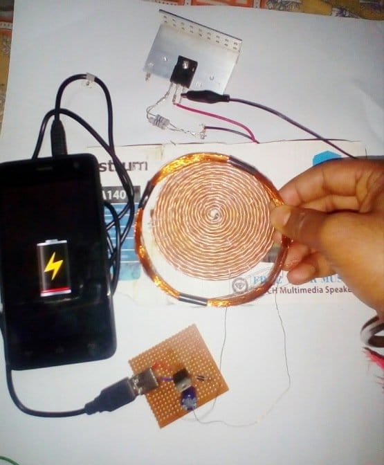
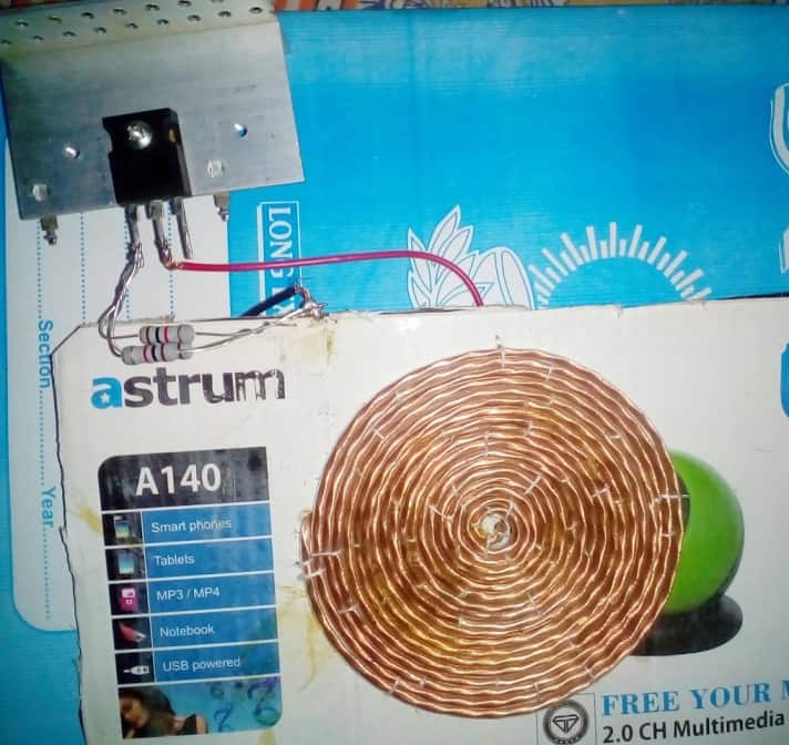
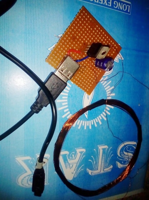


Discussion & Solutions
Sir how much distance between transfer coil or receiver coil
not more than 1 inch
hello sir, avid reader, first attempt at one of your many informative circuits. Just to clarify the main power source for the transmitter reads 12.5 volt 11.5 amp in description but in the picture it shows only 1.5 amp since the 11.5 might have an extra accidental one only because I've never heard of such a high amp DC power source sorry to bother and please never stop teaching, your ability to clarify electronic circuitry has been second to none a long overdue thank you is owed , sincerely Michael Shoop
Thanks Michael, It looks like a typo in the article, it should be 1 amp actually, or may be 2 amps….not more than that.
I'll correct the mistake soon.
Sir i want to know if this circuit is working i wAnt to make it for my project
Chara, I have tested it using flexible wire coils, but not with PCB yet, but I am sure it will work in this mode too, if optimized correctly.
sir i tried it by making different four coils every two coils joining required points but not placed like you showed but when i connect 6volts source transistor burnt.i connected all elements as you showed in picture.What can i do to perform surely?please help me.
Mohammad, I am not sure exactly how you might have connected the elements, but you can try correcting or troubleshooting the circuit by first using a 3V supply and by checking the response of the Rx at touching level..if it works then you could increase the voltage gradually until the transistor is felt warm…then you could increase the turns for reducing the warmth on the transistor and proceed so on..
Hello again sir. I tried to constuct the circuit on breadboard but it is not working. I think theres a problem with the coil. is the number of coil turns on the transmitter the same also with that of the receiver. Sir please help me out. Thank you.
Hello chara,
you made the coils on breadboard?? please explain your prototype so that I can locate the fault.
you need to do exactly as shown in the above article, if you are not able to make the PCB layout coils, then replicate it with wire coils which should be exactly identical to the PCB configuration.
the receiver coil numbers is not crucial, more number of turns will more voltage and vice versa.
Thank ypu for the answer sir. i want to ask again if what type of copper wire(coil) was used?
you can use any super enameled copper wire or pvc flexible wire…
what swg wire is required to make coils?
any gauge wire do initially, it's related to current so won't affect the transfer operation in any manner.
It's the same magnet kicker principle!
Hello sir
Was trying the same on a pcb with 24 gauge copper wire ..
But transistor burnt …
Plzz help with solution
see this video:
https://www.youtube.com/watch?v=4UmVLfFNx7U
Back EMF occurs in between transistor switching, when the magnetic field of the coil collapses (which is what makes it self-oscillate). This back EMF can be a spike of high voltage depending on the coil design. I suspect this is what is burning out your transistor. Try placing a 1N4001 or 1N4007 diode between the collector and power supply. This blocks the back EMF current from re-entering the collector. You may also want to protect the emitter/base junction with a 1N4001 by wiring the striped side of the diode to the base and other side to the emitter. For an example, just look on google for any "Bedini SSG" circuit which protects the transistor in the same manner.
I don't think back EMF could be the problem, because it's a self oscillating circuit and not induced by an external agent, I have never seen a diode being used in self oscillating circuits for back EMF protection….may be because the coil turns are significantly less and the frequency is high.
the problem could be due to a wrong wiring, or wrongly connected coil, or a mismatch between number of turns and input voltage.
Hello watched that video
Done editing but still there is no output in my secondary coil .
BTW i m using a old samsung mobile adapter as power source whose output is 5.13vdc.plzz help
hello sir, why its not work in my project. i was trust your tutor but not work. i make coil 18 turns in transmiter n power adapter 12v/1,5amp, in receiver i make coil 24 turns. but its not work 100% . pls help 'me.
I have checked it myself and it worked for me, see the video above for more info, if still you cannot make then sorry i can't help.
Could the transmitting coil be made on transparent printer film (like the film used to transfer toner to PCB when making your own boards) and conductive ink? I was thinking of the cost of copper clad or having a 10×10 inch PCB made which would cost a lot. My idea is to use 2 sheets (legal paper size) of the transparent film and use conductive ink to draw the coil design on one sheet. Then insulate by placing another sheet over it. Use solar panel tabbing/wire to make connections with conductive glue or tape. This would also be a very thin design. Question is … could it handle the current? I'd probably have to draw the traces pretty thick and wide. Ideas ???
That's possible if sufficiently thick and wide tracks are created with the ink, because the track thickness and width will determine how much current it can handle and can be manipulated by the designer….or alternatively the receiver section can be simply implemented using a pancake kind wire assembly, as shown in the video, because the compactness of the receiver may be not so important.
I've taken the time to design this on a 4×4 inch PCB in Eagle CAD if anyone's interested. Willing to share as long as the files are not altered in any way. DRC rules pass for production @ OSH Park.
Hello sir I have many question regarding this post .Are you tested this circuit. I have not more knowledge but I think than induce current is only for AC current . Sir you use 12 volt 1.5 amps. Can I use an invertor battery of 12v/180amps .
Please clear me what is SWG Number of copper wire and number of turns .
Please reply soon .
Thanks in advances
Hello Kuldeep, please go through the comments, and you'll also find video link which you can refer for more info.
if you are new then I would recommend NOT to try this circuit because it can be very difficult for anybody who does not have a thorough practical and theoretical knowledge of electronics.
Pls sir I used 2N2012 it worked fine ,had a voltage of 5v at the receiver but wasn't able to charge my phone .why?
An sir pls can the distance be increased? How so?..thanks. Please reply soon
I am glad you could succeed with the project, the cell phone might not be charging because of low current, try increasing the input current and check the response….or you can also try decreasing the distance between the Rx and the Tx
sorry the distance range cannot be increased by much, that will strictly affect the performance of the output
Can I use BC547 IN PLACE 2n2222
NO, you can use other higher rated BJTs than 2N2222, but nothing lower than this.
Please suggest me any other transistor . please reply me soon . please give me many choice please.
you can use a BD139, D1351, D880, D313, SL100, TIP31 or any similar
Hello sir i made this circuit it is working good but I use 2N3904 and it get hot on few minute so please give name of a better Transistor .I also use BD139 but it not work
That's great Kuldeep, however BD139 should also work may be it's faulty or not connected correctly.
you can try the other alternatives as suggested in the previous comment…a TIP122 can also be tried
8050 can also be a good candidate.
Sir,
I made it but one problem,
I get sufficient voltage in receiver but current is not sufficient. So showing the mobile is charging but mainly it's not charging or charging too slowly.
So,plz tell me how can I increase the receiver end current ?
I used 12V, 1Amp transformer for power supply.
Narottam, try adding more number of coils parallel with your existing receiver coils, this will help to induce or absorb more current from the transmitter…also make sure the Tx transmitter is supplied with sufficient current from the power supply.
I am afraid 12v 1amp will not do….use a 15V 3amp or 5amp..
I would be interested to see the pics of your design with full details…it would help the many readers to understand the concept better,
sir me Kuldeep Tripathi i make this circuit but i have a question related this circuit . When I supply 3 volt and 1000 milli amp so the reciving volt is 6 v please help me i want to charge my mobile of 1800 milli amp
Vaibhav, do you mean to say you are getting 6V at the receiver end? If it so then you can still use it for charging your cell phone by adding a 5 ohm resistor in series with the output.
Sir, I would like to give you a lot of thanks for showing my projects design in your blog.
The pleasure is all mine, Narottam…
Hello sir..
Can give me all components that's use for this project… And give the value
Hi sir I have a new idea regarding this project . why we not use this circuit as a hand gulf . how future stoic it look .
Please make some comments on this idea
Hi Kuldeep,
sorry I did not understand your point…how can it be used with hand gloves?
Sir,
In transmitter circuit how can produced high frequency power ?
By using transistor, but for transistor switching needs a continuous pulse,here the transistor from where get that type of pulse ?
Please explain…
(Actually my teacher asked me that type of question but I can't explain properly.)
Narottam,
the working of the above design resembles to a "blocking oscillator" functioning, where the transistor is switching is blocked and released at a rapid rate resulting the generation of pulses. This happens due to the coil feedback tap.
https://en.wikipedia.org/wiki/Blocking_oscillator
Ok…thank you…#Sir…
Sir I made that transmitter from your above diagram of transmitter
But it is not working