In this post I have explained how to make a chasing "WELCOME" display circuit sign board, which illuminates each alphabet sequentially until all the 7 alphabets are lit and then the whole display shuts off, the cycle continues permanently as long as the circuit is powered.
Overview
I have already discussed a similar concept explaining a bar graph display LED circuit for car turn signal, the same idea is implemented for the present welcome chasing light display circuit.
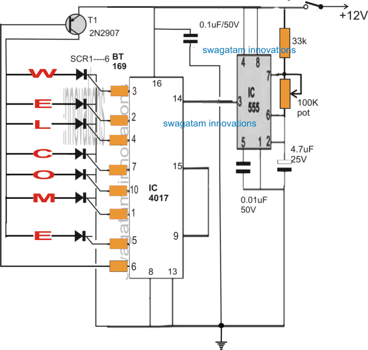
The figure below shows the details of the circuit:
Circuit Diagram
Parts List
All Resistors are 1/4 watt 5%
- SCR gate resistors are all 1k.
- T1 base resistor is 1k
- 33k = 1no
- potentiometer 100k = 1no
- Capacitor 4.7uF/25V/Electrolytic = 1no
- Capacitor 0.1uF/Disc = 1no
- Capacitor 0.01uF/Disc = 1no
- T1 2N2907 = 1no
- IC 4017 = 1no
- IC 555 = 1no
- SCR BT169 = 7nos
How it Works
Referring to the circuit above, the entire design is configured around a standard IC 4017, and IC 555 chaser circuit, wherein the IC 555 transmits the required sequences clocks at pin#14 of the IC 4017 and enables a sequential chasing of the high logic across the selected output pins of the IC 4017.
Here the pinouts from pin#3 and pin#5 are rigged for illuminating the "welcome" display while pin#6 is used for resetting the sequence after each complete cycle.
Meaning once the whole "welcome" sign is lit, subsequently pin#6 triggers the 2N2907 to switch OFF the SCRs and reset the sequence from the beginning at pin#3.
The 4017 IC outputs sequence with a "jumping" high logic which switch ON only momentarily while shifting from one pin to the next, this implies that if the LEDs were connected directly with the pinouts would cause each alphabet to illuminate only for a moment until the next alphabet was lit, enabling only one alphabet to be lit at a given instant. This would make the display unreadable and the "welcome" sign would be unrecognizable.
In order to ensure that all the alphabets are lit and stay latched during the sequencing, SCRs are introduced with the pinouts for illuminating the LEDs.
The SCRs trigger and latch during the sequence until all the the alphabets are illuminated and then finally shut off to begin a new sequence.
The IC 555 generates the clocks for the sequencing, and the speed of the sequencing can be adjusted through the associated 100K pot.
How to Wire the LEDs for Creating the WELCOME alphabets
Now I have explained how all the alphabets involved in the display may be wired using many LEDs in series and parallel connections.
Since the supply for the circuit is around 12V to 15V, and assuming the LEDs are 5mm/20mA type red LEDs, wiring groups of 4 LEDs in series seems to suit the best.
The following example figure clearly illustrates how the letter "W" may be wired using groups of 4 series LEDs, and connecting these 4 LED strings in parallel, such that the final outcome resembles the letter "W".
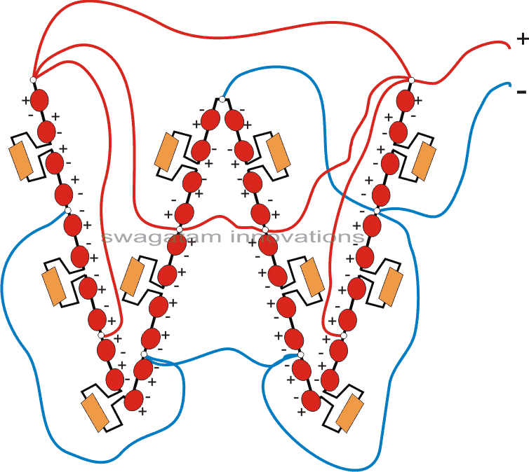
In the same way other alphabets could be easily configured and wired together for developing the required "welcome" chasing LED display circuit.
The series resistors across each of the 4 series LED string can be calculated using the linked software.
All LEDs are red LEDs/5mm/20mA/High Bright
For 4 LED series the resistor value will be = 25 Ohms 1/4 watt
If there are 3 LED series the resistor value will be = 175 Ohms 1/4 watt
If there are 2 LED series the resistor value will be = 330 Ohms 1/4 watt


Comments
Hi Swagatam,
I asked a question a couple of days back and I can't remember where I asked it, so I am asking again under this post. My question is: can I use 2-12vdc power supplies in series to light 24v strip LEDs? The seller sent me 24v strip LEDs instead of the 12v I ordered. I'm trying to figure out how I may use them. Thanks!
Hi Swagatam,
My question relates to the 555 resistors. I have previously used 4.7K for the 33K, 100K pot and 10uF for the 4.7uF with success in the past. What is the real difference between the two configurations? Just trying to learn. Thanks!
I make this circuit but not work properly pls send me any link or send me video link
Thanking you
Dear sir
what problem are you getting? you should first check using single LEDs with 1K resistors, and then wire the alphabets accordingly for the final integration
Sir pls send the lind address
here are the links
https://www.homemade-circuits.com/2012/03/how-to-make-simple-scr-application.html
https://www.homemade-circuits.com/2013/02/make-these-simple-cheap-home-burglar.html
Here the resistance value with SCR not marked.pls specify value of registace
you can use 1k resistors
Thank u sir …for your nice and good explanation
One more doubt sir
1.While giving single postive trigger 1 second to Scr ..it will conduct….?
2.When we give continues postive trigger scr will damage ?
3.SCR & TRIAC latch continues means we can use for alarm circuit…when small postive trigger apply to gate…it will make continues alarm….
…
1) yes single trigger will latch the SCR
2) multiple triggers will not damage the SCR
3) we can use this feature for making security alarm which I have already published in this website
For SCR we can use transistor….?
Pls tell the difference of SCR & TRANSISTOR…it will work only in DC…
TRIAC will work only in AC…
MOSFET will work in DC..?
Sometimes I'm confused seeing some circuits in web….so pls explain sir…
transistors will not latch and not hold the illumination, that's why SCRs are used which will latch and keep the LED locked until broken through T1.
SCR and triac will work with AC, without latching….but in DC they will latch with one trigger.
mosfet and BJTs can never work with AC.