• Skip to main content
  • Skip to primary sidebar

Homemade Circuit Projects

Need circuit help? Post them in the comments! I've answered over 50,000!

Blog | Categories | About | Hire Me | Contact | Calculators-online
You are here: Home / Power Supply Circuits / 1A Step-Down Voltage Regulator Circuit – Switched Mode 78XX Alternative

DIY Circuits | Learn Basics | Arduino Coding

1A Step-Down Voltage Regulator Circuit – Switched Mode 78XX Alternative

Last Updated on January 19, 2025 by Swagatam 4 Comments

You will be amazed with the features offered by this outstanding voltage regulator IC. As the name refers to, the output from this series of ICs is not only regulated and stabilized but is in the form of switched pulses at very high frequencies.

Enhanced Version of the Popular 78XX ICs

These ICs may be considered as an improved SMPS alternative for the conventional linear IC 78XX series regulators which tend to become hot with rising currents at their outputs, but not a problem with the series LM2575 from TEXAS INSTRUMENTS.

The switched output with the LM2575 series of ICs especially enables to implement very efficient power transfer to the load even at currents as high 1 Amp.

The switched output saves power, keeps the IC cool so that no heatsinks are involved,  moreover the switched output makes the IC particularly suitable for a wide application range like in LED drivers, battery chargers etc.

These will be discussed elaborately in my coming articles.

The LM2575 series from TEXAS INSTRUMENTS provides all the features which particularly becomes very ideal for buck step down regulator applications.

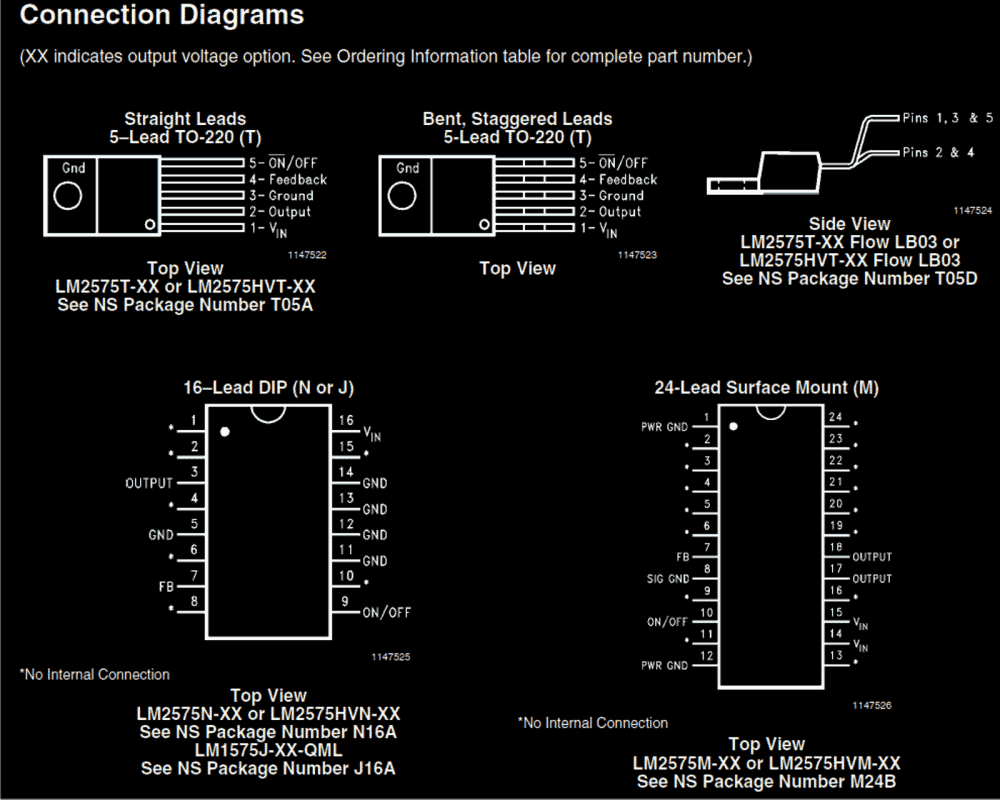
These devices are typically capable of producing fixed regulated outputs of 3.3V, 5V, 12V, 15V, and also an adjustable output from one of the devices.

The configuration around these ICs require very few number of components for enabling it to function as an effective voltage regulator circuit.

The IC necessarily employs an inductor, as we all know that an inductor specifically becomes imperative for all buck/boost type of applications, so even this chip requires one.

Though this inductor my be readily procured from the market, may also be hand made using appropriate sized wire and number of calculated turns.

Main Technical Specs

The main features of the IC LM2575 may be summarized as follows:

Output - 3.3V, 5V, 12V, 15V and also an adjustable version configurable.
The adjustable version is able to provide outputs in the range of 1.2V to 35V, 57 volts being the highest.

Current - A assured 1 amp of current may be expected from these chips.

Input Voltage - A broad DC range upto 40 or even 60 V may be used as inputs for these ICs.
Operating Frequency - The ICs output fluctuates at a fixed frequency of 52 kHz, which is set internally.

Protections - The chips are all internally safeguarded from over heating and over current.

Courtesy of Texas Instruments: ti.com/lit/ds/symlink/lm2575-n.pdf

IC LM2575 pinout details


You'll also like:

  • buck converter CM DM modesSimple Buck Converter Circuits using Transistors
  • 5V LDOSimple Low Dropout Regulator Circuits Explained
  • 317hv0-60V LM317HV Variable Power Supply Circuit Diagram
  • 317 2LM317 with Outboard Current Boost Circuit

Filed Under: Power Supply Circuits Tagged With: Down, Mode, Regulator, Step, Switched, Voltage

About Swagatam

I am an electronics engineer and doing practical hands-on work from more than 15 years now. Building real circuits, testing them and also making PCB layouts by myself. I really love doing all these things like inventing something new, designing electronics and also helping other people like hobby guys who want to make their own cool circuits at home.

And that is the main reason why I started this website homemade-circuits.com, to share different types of circuit ideas..

If you are having any kind of doubt or question related to circuits then just write down your question in the comment box below, I am like always checking, so I guarantee I will reply you for sure!

Previous Post: « Make this Temperature Indicator Circuit with Sequential LED Display
Next Post: Making an Adjustable Electromagnet Circuit »

Reader Interactions

Comments

nitin chaudhari says:
October 5, 2019 at 1:14 pm

But current required is 9A which diode can be used?

Reply
Swagatam says:
October 5, 2019 at 2:21 pm

I that case you can try the following concept:

https://www.homemade-circuits.com/wp-content/uploads/2012/08/simplestDCcellphonechargercircuit.png

Replace the zener with an adjusted 14V zener diode.

Also replace the transistor with a TIP142

Reply
nitin chaudhari says:
October 5, 2019 at 12:15 pm

Hello sir,
How to drop 15 v dc to 13.5v dc?

Reply
Swagatam says:
October 5, 2019 at 12:50 pm

Hi Nitin,

put 2 or 3 rectifier diodes in series with the positive line

Reply

Need Help? Please Leave a Comment! We value your input—Kindly keep it relevant to the above topic! Cancel reply

Your email address will not be published. Required fields are marked *

Primary Sidebar

circuit simulator image

Subscribe to get New Circuits in your Email

Categories

  • Arduino Projects (96)
  • Audio and Amplifier Projects (133)
  • Automation Projects (18)
  • Automobile Electronics (103)
  • Battery Charger Circuits (87)
  • Datasheets and Components (109)
  • Electronics Theory (149)
  • Energy from Magnets (27)
  • Games and Sports Projects (11)
  • Grid and 3-Phase (20)
  • Health related Projects (27)
  • Home Electrical Circuits (13)
  • Indicator Circuits (16)
  • Inverter Circuits (96)
  • Lamps and Lights (159)
  • Meters and Testers (72)
  • Mini Projects (28)
  • Motor Controller (68)
  • Oscillator Circuits (28)
  • Pets and Pests (15)
  • Power Supply Circuits (91)
  • Remote Control Circuits (50)
  • Renewable Energy (12)
  • Security and Alarm (64)
  • Sensors and Detectors (106)
  • SMPS and Converters (34)
  • Solar Controller Circuits (60)
  • Temperature Controllers (43)
  • Timer and Delay Relay (49)
  • Voltage Control and Protection (42)
  • Water Controller (37)
  • Wireless Circuits (31)

Other Links

  • Privacy Policy
  • Cookie Policy
  • Disclaimer
  • Copyright
  • Videos
  • Sitemap

People also Search

555 Circuits | 741 Circuits | LM324 Circuits | LM338 Circuits | 4017 Circuits | Ultrasonic Projects | SMPS Projects | Christmas Projects | MOSFETs | Radio Circuits | Laser Circuits | PIR Projects |

Social Profiles

  • Twitter
  • YouTube
  • Instagram
  • Pinterest
  • My Facebook-Page
  • Stack Exchange
  • Linkedin

Recent Comments

  • Swagatam on How IC LM337 Works: Datasheet, Application Circuits
  • Swagatam on Make a Simple Class D Amplifier Circuit
  • Mehmet Ovacıklı on How IC LM337 Works: Datasheet, Application Circuits
  • Swagatam on EGS002 Datasheet, Circuit Diagram Explained
  • Nnadi on EGS002 Datasheet, Circuit Diagram Explained

© 2026 · Swagatam Innovations