Here I have explained about a couple of simple circuit configurations which will convert any low power inverter to a massive high power inverter circuit.
You'll find a plenty of small and medium sized inverters in the market ranging from 100 to 500 watts, the same may be seen posted in this blog. Upgrading or converting such small or medium power inverters into massive high power inverter in the order of kvas may look quite a daunting and complex, but actually it's not.
Analyzing Inverter Topologies
All inverter topologies basically incorporate an oscillator frequency which is then amplified using power devices to high current levels before dumping into the step-up transformer for the final voltage boosting procedures.
The current amplifier stage which employs high current devices is where the upgrade needs to be done in order to achieve any desired power outputs from an inverter.
The modern day inveters heavily rely on mosfets for the above mentioned power conversion stage, nevertheless BJTs can be also used for the same very effectively, in fact much reliably than mosfets...
How to Upgrade Low Power to High Power
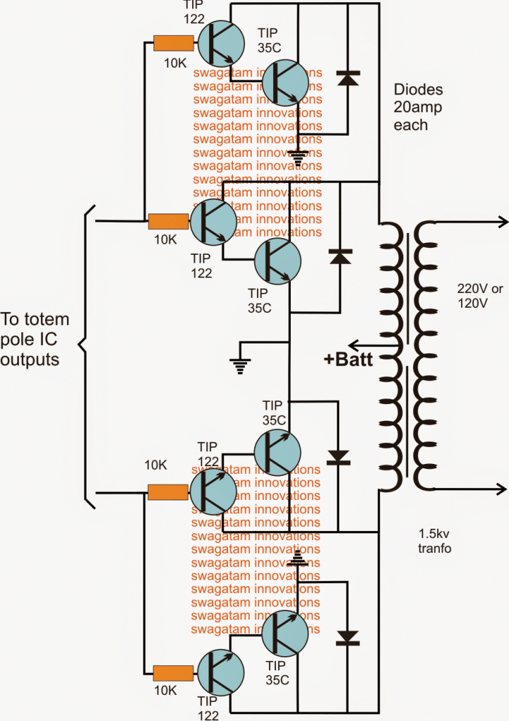
The following diagram shows a simple and very effective power output stage which can be integrated with any totem pole IC outputs such as IC 4047, IC TL494, IC SG3525, IC 4017 (clocked with IC555), for acquiring upto 1.5kva conversions.
The key devices in the circuit are the combination of the TIP122 and TIP35 which become a high gain, high current transistor pair, capable of boosting current to the rated massive levels instantly.
Each such device module is rated to produce at least 30 x 24 = 720 watts, so by adding more such modules in parallel any desired kva range can be anticipated from the configuration
Using Power BJTs
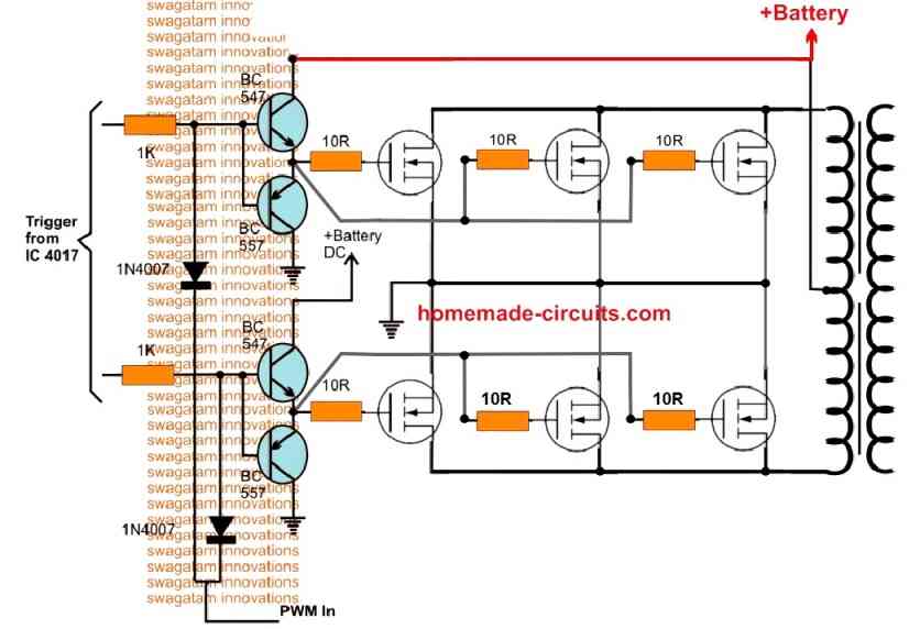
Using BJTs could be very reliable and simpler but quiet bulky, if space is your problem and need the upgrade from low to high power inverter in the most compact way, then mosfets becomes the popular choice and may be wired as shown in the following diagram:
The input is derived again from any totem pole IC outputs, the MOSFETs could be rated as per the desired upgrade from lower to the highest magnitudes.
The diode integration suggests a simple PWM insertion which is optional, but could be used if a modified sine wave output intended to be included in the upgrade.
Adding MOSFETs in Parallel
The above explained ideas for upgrading a low power inverer circuit to a higher power version can be implemented to any desired level, simply by adding several MOSFETs in parallel.
Adding MOSFETs in parallel is actually easier than adding BJT in parallel. It's just about connecting the all the drains, and all the sources together, and then joining all the gates together through individual 10 ohms resistors.
Upgrading Transformer and the Battery
MOSFETs are like switches, which means that only by upgrading the MOSFETs will only bolster the switching part to handle higher wattage and current. However, to actually achieve the desired high output wattage, the transformer and the battery rating will also need to be upgraded accordingly.
For example, if the a 100 watt inverter is upgraded to 500 watts, then the along with the MOSFETs, the battery Ah and the transformer wattage will also need to be increased to the intended 3 times or higher values.
The above explained simple strategies would be enough to enable you to upgrade, or modify, or convert any small or low power inverter design into a high power inverter circuit with the desired wattage specs.


Questions & Answers
Good afternoon Sir,
Sir you said in the opening paragraphs here that BJTs are more reliable than MOSFETs. Does it mean constructing an inverter with BJT is preferable?
Good afternoon NGANG,
Yes, BJTs can be used with great reliability for inverters below 1000 watts. Above 1000 watts you may have go for MOSFETs.
sir, how do I upgrade 200w mini inverter to 500w.
Hi Loli, you can upgrade the MOSFET power by adding more numbers in parallel as shown above.
Increase battery capacity or the Ah rating 3 times more, and do the same for the transformer.
Hi, Swagatam, I am trying to get a large solar battery to charge itself. I want to plug into its 12v dc port on left side and bump up current via 2000 watt inverter and plug that current into AC charging port on right side. Company says it’s possible but incoming AC must have 700 watts. Problem is, I can only get 150 watts out of cigarette lighter style dc source. So…I am a writer and understand almostnothing of the technical talk on your site. What kind of professional do I need to contact to have a circuit board I need to make my idea work? Willing to pay honest person for his labor, of course. Any reliable referrals much appreciated! Many thanks for any ideas!
Hi Jim, I understand your problem, however unfortunately I do not have anybody within my reach whom I can refer your job to. You can probably try the online services such as freelacer, upwork etc to hire an appropriate technician for the task.
Hey mate, I have some inverters which are rated for 1500watts but keep dying at around 1100 surge. I have 15 of them and wondering if you might be able to help me understand if I can do an upgrade to save my business? Could you email me or could we zoom, happy to pay for your time, thanks!
Hey James, an inverter will die most probably due to burned mosfets or burned power devices which control the load. If the power devices are overloaded then they are going to die soon.
You can upgrade your inverter by adding more number of mosfets in parallel. You must also make sure that the transformer is rated correctly to handle the output max load.
I will be most happy to help you here through this commenting platform. It would be great if you could also comment under other relevant posts.
Hey, these are all brand new inverters from China, all of them are showing the same issue. The original shipment handle 1500watts easily, the company has swapped the inverters and the result is as above. I have taken an inverter board out of the system and trying to figure out my next plan of action. It seems as if there are quite a few large mosfets on this “1500” watt 24v inverter. I will also have to figure out how the transformer is rated.
OK no problem, all the best to you!
Hi Swagatam
Do I connect the output from my small ups direct onto this upgrade, or to the IC’s input that you mention here
Also if I got a pure sinewave small inverter, will my high power output also be pure sinewave?
Hi Giel,
If you are having a full fledged small inverter with battery, transformer and mosfets, then you just need to upgrade these 3 elements to increase the power of the inverter. For the mosfets you just have to add a few of them in parallel across each channel, along with this you will have to upgrade the battery and the transformer wattage specifications accordingly.
Yes, if the oscillator circuit around the mosfets is sine wave then the upgraded inverter will also produce high power sine wave output.
If a high ampere battery, say 200ah is connected to 100watts rated Inverter, will it destroy the inverter?
No it will not, the high Ah rating will not matter as long as the battery voltage is as per the inverter specifications.
Sir pls, how can i convert my 1kw inverter to 4kw using irf3205
Chukwuma, Please see the last circuit, you can implement that for your application. You will need at least 5 to 7 parallel mosfets on each channel, and a 36 V or 48 V battery
How will this impact an inverter rated for 12V if you boost the power output of a 1Kw to say 3Kw. Will connecting a 24V battery be possible.
You can divide the wattage by the battery voltage that will tell you how much current will be required for the mosfets to handle and for the battery/transformer to deliver.
Currently the Inverter has 4xG40N60 (40Amp 600Volts) at 12Volts. I intend to replace these with 4xFGH40N60SMDF (80amp 600Volts). Transformer will be 24V 150Amps. Will I need to reinforce the tracks on the PCB to prevent them from burning up due to the higher power output.
Yes you should reinforce the tracks with layers of solder or copper wires to ensure it is able to handle the high current
Hi there.
Love your site. I want to know , how can I upgrade my 800w inverter to 1500w – samlex
And my 1000w inverter to 2000w – Fivestar
It is for my 2 seperate households
I am using your upgrade of the 300w, but upgrading 4 times. I will give my feedback. 🙂
Hi, thanks for liking my site, appreciate it. You can try adding more number of mosfets in parallel, at least 5 more in parallel to the existing ones, and also upgrade the battery Ah rating accordingly.
The world is in chaos. Climate change is Rampant. One of the proposed solutions is changing from fossil fuels to electrical powered vehicles, however such power use to charge batteries poses a further strain on our already stressed power grid system. Nikola Tesla patented a process for extracting electricity from the aether. In the book Les Brown Pyramids is described a similar system for extracting electricity. We intend to conduct experiments to determine if this is a possibility. If we are successful we will need inverters to convert high voltage DC to 110 and 220, three leg alternating current sufficient to run an individual household, ideally dual 5000 kilowatt systems designed to provide backup in case of failure of the primary system. The components need to have a low operating temperature below 0 degrees Centigrade. Can you provide information on modifying your systems to provide these parameters. The contemplated input voltage would be 330 volts to provide for an up to 220 volts pure sine wave inverter.
I am sorry I don’t think I will be able to do it, i can only suggest general inverter concepts, the specialized ones are beyond the scope of my expertise!
Saludos,,,,,,Ing. preguntó cuánto sería la resistencia que debo de usar en las salidas del ci 4047 en pin 10 y 11…..hay un Rango estimado o es diferente para un Bjt y el mosfet..
Greetings, if you are using MOSFETS then the 4017 output resistors is not critical, can be any value between 1k ohm, and 10k ohm
can i plug a 1000 watt transformer into my 200watt flashfish generator. if i can then the 1000 watts can be used to make coffee.
You can only if the voltage specs of the 1000 W is similar to the existing 200 W system…
Sir! <thank you for your excellent site 🙂
I hope you can help me, I have a bunch of 230/12V 23A transformers, I'm planning to use 3 in parallel to make a 900W inverter based on your 500W inverter design. Unfortunately the transformers don't have a mid tap, they are 2 wire. I also have a bunch of IXQT13N10P, can I use them in parallel? If not, I do have some K2837 and some IRF3205PBF, can I use any (or some?) of these in combination or parallel to archive my goal? I'm planning to use a 24V battery bank of lead-acid batteries consisting of equal 12V batteries in series/paralell (or would 12V be easier)?
Hello Karstein, yes paralleling may be possible but only at the primary side, not on the 220V side. Before that try with a single transformer to confirm the working, using the following concept:
Simplest Full Bridge Inverter Circuit
The MOSFeT should be exactly as suggested in the above link, other FETs can be tried if they have exactly matching specs.
Good day sir..Engr. There is a foreign inverter Ferrite core transformer…the out high voltage 310VDC complete, but the switching system, for load regulator is not working, please can you help with a circuit that could switch the MOSFET at the out put stage….please help me….
Thanks
Hi Sunshine, if you referring to the oscillator section, then probably you can use the IC 4047. Adjust its output to 100 kHz, feed the frequency to the MOSFETs, then gradually reduce it until you get the most optimal result from the inverter.
Hi
I want to built 3.5kva 48v to 2220v sinewave inverter can you assist with the part lis and cicuirts board
You will need a 80 amp 48 V transformer….many IRF3205 mosfets an the IC 4047 oscillator circuit.
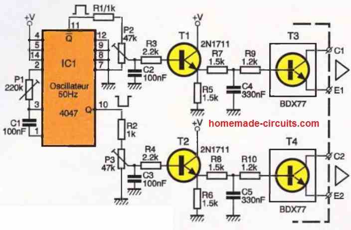
the basic design will be as given below:
500 Watt Inverter Circuit with Battery Charger
sir. i have a 200w inverter which is not design with ics. so pls sir can u explain how i can connect it with the above circuit. cos i see its connected to the ICS here.. am still a fresher in electronics though
Olatunji, if you are already having a fully working inverter then you can simply check the output power devices and replace them with more powerful devices. No need of making the improvements suggested in the above article.
I am sure your inverter would be using mosfets for the power devices, you just have locate them and replace them with more powerful mosfets, as per your desired specifications.
And yes, this would work only if your transformer and battery are also accordingly upgraded.
I tried to post my question but it seems like it didn’t post.
Dear please provide me a circuit which can be used after my 150v DC smps to control/vary voltage and limit current….volt/current adjustable.
Thank you..!
You can try the following circuit,
https://www.homemade-circuits.com/0-300v-variable-voltage-current/
ignore and eliminate everything that’s on left side of C1
sir please how can i connect a relay in the inverter so that it can automatically switch to the mains when the mains is on,and ratings of the relay. 200w inverter
olatunji, you can follow the following concept
https://www.homemade-circuits.com/how-to-convert-inverter-to-ups/
sir i wish we have a kind and honest person like you in our country to enlighten novice like me in my country too
All thanks to your quick and fast reply i am able to turn my small ups into a 3000watt pure sine wave inverter within two weeks i pray the lord shall always strengthen you to continue the good work of yours
sir i nose around for months but your site is the king of site sir i mean the best i wish more people like you will stand up to enlight
more people like me thanks
You are most welcome abioye, please keep visiting my site, and keep up the good work
Sir please explain the way you calculated power? 30*24=720 How?
30 is the voltage that possibly may be used for powering the inverter and the 24 is the max current rating of the transistor.
How many volt should i apply to the collector of that bc547 must it be 12volt?
yes it must be 12V, and the trafo center tap must be separately powered with the battery positive if it's higher than 12V
Hi if I was to use you circuit as stated above would the original transformer in the 300w inverter work of I was to modify it to plus minus 800w
Hi, how can a 300watt transformer produce 800 watts, sorry that's not possible.
good day sir, i so much appreciate all your work in this blog, may God continue to guide you. please i need a complete circuit diagram for 1.2 KVa pure or modified sine wave inverter with inbuilt charging section.
thanks
thanks Muhammed, just integrate a 4047 oscillator circuit with the mosfet power stage as explained above, you would be able to achieve the required specs instantly
If I have 500w inverter already and wish to convert to 2000w. How does the mosfets multiply to achieve that. e.g two of such mosfets in parallel will give what… And again is it any mosfet at all or to be chosen according to current and voltage handling capacities.
You can refer to the following article to know all the details regarding how to upgrade the mosfets, transformer and the battery for increasing the inverter wattage:
https://www.homemade-circuits.com/how-to-calculate-and-match-inverter/