Are you wondering if it was possible to build a very simple MPPT circuit using ordinary parts like IC 555 and IC 741, which would work most efficiently imitating a true MPPT? The answer is yes, it is possible, and we will learn about it details, in the following article.
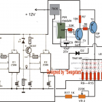
In this design I used the IC 555 as a variable PWM generator. That means the IC 555 here is continuously creating a train of pulses at its pin#3. These pulses decide how fast or slow the MOSFET IRF540 is switching, which means how much power is allowed to reach the battery.
But now the trick part—this PWM pulse width is not fixed, it is controlled from solar panel voltage. That is done using pin#5 of the 555 which is connected to solar panel output through a preset.

If you don't want to read the whole article below, you can watch the following video instead:
How we used ic 555 like pwm generator
So in this idea what we tried is we used that ic 555 as one variable pwm signal producer. That means this ic 555 it keeps giving out one train of pulse signals from its pin 3 continuously.
Then those pulse signals they go and tell the mosfet irf9540 how fast it should do the switching. So now that mosfet it also handles how much current or power is going to battery side.
How pwm width changes with solar voltage
But the special thing here is that width of those pwm pulses it does not stay fixed. It keeps changing depending on how much voltage we are getting from solar panel. So we used that trick by connecting the pin 5 of ic 555 to the output of solar panel through one preset.
Now it is like this, when we are getting more sunlight then that solar panel also starts giving more voltage. Then that higher voltage reaches the pin 5 of ic 555 and pin 5 voltage also goes up. Inside this ic 555 there is that internal modulation part.
When pin 5 voltage increases, then the pwm duty cycle at pin 3 also increases. So this makes the pulse width to become more wide.
That will make us feel like mosfet will stay on for longer time. But that is not true because that mosfet is p-channel type.
So actually the MOSFET conduction actually gets narrow when duty cycle becomes high.
What happens due to all this
When we get full sunlight, that time the duty cycle of the mosfet becomes smaller. That means the on time becomes less.
So now the buck converter takes less energy from the solar panel. So because of this the panel voltage does not fall too much and it remains near that mpp level which is maximum power point.
Then when sunlight becomes weak, the solar voltage also starts coming down. That reduced voltage goes to pin 5 of ic 555 and pin 5 voltage drops.
So again the pwm duty cycle becomes narrow at pin 3. But since it is p channel mosfet, this narrow pulse actually makes the mosfet turn on for longer time.
So now the mosfet gets more on time and because of that the buck converter starts pulling more current from the panel. This helps to keep output power stable.
But we know that panel is already weak in performance, so the circuit automatically decreases pwm and controls the panel voltage so that it does not fall much or get overloaded.
How the circuit balances itself always
So this whole thing works like one balancing system which always adjusts depending on sunlight strength.
How mppt function happens in second part
Now second part of this system makes our circuit work like mppt tracker. That means it tries to follow maximum power point logic.
For this we used one opamp ic 741. It is made in such way that it keeps watching how panel voltage is changing and keeps one past voltage value in memory. That memory is held using some diodes and one capacitor.
So how it is wired and how it works
So pin 2 which is inverting input of opamp gets live voltage from solar panel directly. Then pin 3 which is non-inverting input also gets same panel voltage but it has to go through 3 diodes.
These 3 diodes make voltage drop of around 1.6V. So normally pin 3 stays lower than pin 2 by that 1.6V as long as panel voltage is same or increasing.
There is one 10uF capacitor at pin 3 side which makes voltage drop happen slowly. This helps to hold previous level.
But what happens if voltage drops suddenly
Now suppose the load like battery pulls heavy current because battery is very low. So panel voltage drops quickly. Then this low voltage reaches pin 2 and it falls fast.
But pin 3 cannot fall that fast because that capacitor holds it. So now pin 3 becomes more than pin 2. Then because of this the output of opamp goes high.
What this high output does
This high signal is sent to pin 5 of ic 555. This increases pwm duty cycle at pin 3 of ic 555. So pulse becomes wider. But this again makes gate of p channel mosfet get narrow pwm. So on time becomes short. This reduces output power of buck converter. Then load current becomes less. Because of that, the panel voltage starts rising again.
Final outcome of all this
So this opamp 741 part works like feedback control system. It checks when panel is getting too much load and tries to bring it down fast. Then it lets the panel recover voltage and slowly tries to increase again. This is how the circuit works like intelligent mppt controller.
Buck Converter Inductor Formula
L = (Vin - Vout) × D / (f × ΔI)Where:
- L = Inductance in Henry (H)
- Vin = Input voltage from solar panel (V)
- Vout = Output voltage to battery (V)
- D = Duty cycle = Vout / Vin
- f = Switching frequency (Hz)
- ΔI = Ripple current through inductor (A), usually 30% to 40% of load current
Example: Based on Your Circuit
Let us assume:
- Vin = 18V (solar panel under full sun)
- Vout = 13V (for charging 12V battery)
- Load current = 4A (so ripple 30% of 4A = 1.2A)
- f = 50kHz (PWM frequency of 555 IC)
Example:
Let us assume:
- Vin = 18V (solar panel under full sun)
- Vout = 13V (for charging 12V battery)
- Load current = 4A (so ripple 30% of 4A = 1.2A)
- f = 50kHz (PWM frequency of 555 IC)
Step 1: Calculate Duty Cycle
D = Vout / Vin = 13 / 18 = 0.72Step 2: Plug in Formula
L = (Vin - Vout) × D / (f × ΔI)
= (18 - 13) × 0.72 / (50000 × 1.2)
= 5 × 0.72 / 60000
= 3.6 / 60000
= 0.00006 H
= 60 µH
Final Answer:
L = 60 µH inductor
That means, for best performance of your buck converter with 18V solar input and 12V battery output at 4A load, you should use around 60 microhenry inductor.
You can use toroidal or iron core inductor rated at least 5A current with low resistance for best results.
Pro Tip:
If switching frequency is lower like 20kHz then L will go up:
L = 3.6 / (20000 × 1.2) = 150 µHSo lower frequency = bigger inductor and higher frequency = smaller inductor, but more EMI.
Summarizing:
- 555 makes PWM, controlled from solar voltage.
- 2N2222 flips it, feeds it to MOSFET gate.
- When sun is strong, MOSFET gets less ON time (voltage maintained).
- When sun is weak, MOSFET gets more ON time (current increased).
- 741 compares present and previous solar voltage.
- If voltage falls too fast, it makes 555 give max PWM.
- After inverter, this cuts down MOSFET PWM.
- Load current reduces, panel voltage goes up again.
- Then again PWM increases slowly... cycle repeats.
Comments
Hello! I looked at the above proposed circuit and I notice one error in it – the voltage on the panel cannot be monitored by the OU741, since its input is connected to the stabilized power source for the entire circuit, these are the 18 volts of the stabilizer. In my opinion, the 10k potentiometer should be connected to the plus of the panel…
Hi, thanks for your kind analysis….however the 555 and the 741 are configured to detect the falling voltage from the panel and adjust the output accordingly. The 18V from the regulator only works like a voltage limiter and prevents voltage exceeding the 18V limit, however if the solar panel voltage drops, then the regulator cannot prevent that, and this dropping voltage is detected by the circuit so that it can adjust the MPP level for the battery accordingly…
Hello Swagatam
I sent you the text that was erased. I am writing again very briefly, I hope it will be corrected. Considering the polarity of the diode connecting the output pin of 741 and pin 5 of IC 555, turning the volume to ground will connect the output of 741 directly to ground and damage the IC. The resistance at the top of the potentiometer should be reduced to 50 kOhm and a resistor should be installed at the bottom of the potentiometer.
Thank you for your attention
Hello Amirsaraf, yes, a whole one month data was erased due to a critical error on my website and I had no backups to restore it. Because of that your previous comments and many other comments, along with the modifications in the diagrams were erased and gone, and I am extremely sorry about that.
But no problems, I have now once again corrected the diagram so that the concern that you have mentioned is rectified appropriately.
Please check the new updated diagram in the above article, and please let me know if it is ok or not?
Dear Mr. Swagatam
The circuit is now corrected, and the bypass capacitor was installed, which was very interesting. Thank you for your good work
Thank you Dear Amirsaraf, for your kind analysis – much appreciated…
I saved an image of the circuit you had posted earlier. It is identical to the new one, except in the new version you add some extra information: the label “L1” on the inductor; and the 18V zener in the second image is specified as 1W, while in the first it simply says “18V zener”.
Yes, the new design has a few more additional details. For optimum current, the TIP35 could be replaced with a 20 amp Darlington transistor and the base resistor replaced with a 1k resistor.
Could you simulate the circuit in Falstad? I don’t have enough knowledge, but I did what I could. https://docs.google.com/document/d/1oKrxUz4rNNYMVEfW6taTrMjy_VH3jaLA_hV1e6ZYebw/edit?usp=sharing
I tried but it seems it is not responding. I think we should simulate the stages step wise, fist we can start with the IC 555 PWM stage, then the buck converter, then the IC 741 stage, and finally the feedback stage…
Hello Swagatam,
I am an engineer, although I am far from being an expert in electronics (I would very much like to be). I’m writing from Chile. Over the past few weeks, I have been researching different types of controllers to make the use of PV solar panels for water heating as economical as possible—without sacrificing too much efficiency and while keeping the system robust. I am considering a setup with 6 panels and a power limit of no more than 3 kVA, ruling out commercial inverters due to their high cost.
It seems to me that an interesting option could be an analog controller, although I’m not sure if it would be feasible to achieve that level of power economically and reliable. I have seen different strategies (analog multiplier, fixed Vmpp, current-based tracking) that I don’t fully understand. I have also come across digital alternatives using Arduino or other devices, with various methods (P&O, incremental conductance, fixed Vmp table, or lookup table).
Most controllers are designed for charging batteries, which requires precise voltage regulation and control systems to prevent overcharging. In my case, however, the application should be simpler: I only need to operate at the MPP, and on the load side we can simply select a suitable resistance from what is available on the market.
Could you please guide me on which direction would be best to focus my search?
Thanks!
Hi Ignacio,
If you can build it yourself, then I would suggest you the last circuit given in the above article. It looks a good fit for your requirement, and it has all the features, such as automatic MPPT control, overload control and battery overcharge feed back control, and is simple also.
Let me know if you have any further questions regarding this design….
Hi Swagatam,
Do you perhaps have a circuit to protect my solar system from lightning strikes?
Regards
Jan
Hi Jan,
The only way I an aware of is to connect a tall copper rod above the solar panel, and then insert the lower section of the rod deep inside the soil, packed with lots of salt and water.
How about getting a small solar panel and connecting its max power (minimal) resistor across it. The voltage across it should be a measure of the sun’s intensity. This signal could be used to drive switching circuit for an array of big solar panels (orientated similarly) to drive a heating element. (I only want hot water energy storage) Could use an Arduino to include a template function to match the panel to signal.
Now how to calculate (1) optimum pwm frequency (2) inductor value (3)capacitor value
That’s definitely possible. Frequency can be anything between 50kHz and 100kHz, it is mainly a measure of how small or how big the inductor needs to be.
Inductor value can be calculated using the following software, and capacitor value is not critical, the higher the better:
https://www.homemade-circuits.com/buck-converter-calculator/