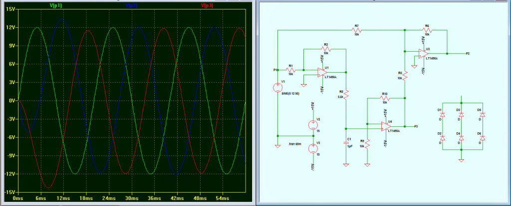
Many a times we find it crucial and handy to possess a true three phase signal for evaluating many different electronic configurations such three phase inverters, three phase motors, converters etc. Since it’s not so easy to incorporate single phase to three phase conversion quickly we find this particular implementation difficult to acquire and enforce. […]
Opamp
Simple Ultrasonic Sound Sensor Alarm Circuit using Opamp
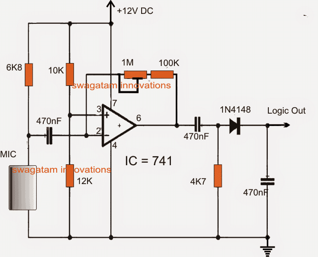
This article discusses a simple ultrasonic sound sensor alarm circuit which may be appropriately set for detecting sound pressures well above the normal human listening capacity, that may range from 20 kHz and over. Ultrasonic Concept Ultrasound or ultrasonic sound waves was probably invented even before humans existed on this planet by a few of […]
Sine wave PWM (SPWM) Circuit using Opamp
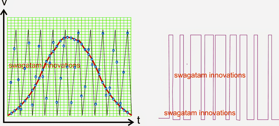
SPWM refers to Sine Wave Pulse Width Modulation which is a pulse width arrangement in which the pulses are narrower at the start, which gradually get broader at the middle, and then narrower again of the end of the arrangement. This set of pulses when implemented in an inductive application like inverter enables the output […]
Opamp Hysteresis – Calculations and Design Considerations
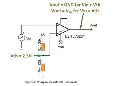
In most automatic battery charger circuits in this blog you might have seen an opamp with a hysteresis feature included for some crucial function. In the following post I have explained the significance and design techniques for the hysteresis function in opamp circuits. To learn exactly what’s a hysteresis you can refer to this article […]