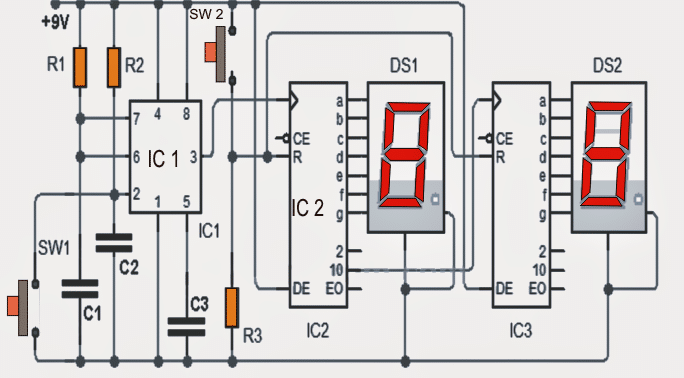
• Skip to main content
  • Skip to primary sidebar

Homemade Circuit Projects

Need circuit help? Post them in the comments! I've answered over 50,000!

Blog | Categories | About | Contact | Calculators-online
You are here: Home / Archives for Diagrams

Diagrams

10 Useful Function Generator Circuit Diagrams Explained

Last Updated on January 17, 2025 by Swagatam 27 Comments

function generator circuit

In this post I have explained how to build 10 simple yet useful function generator circuits using IC 4049, IC 8038, IC 741, IC 7400, transistors, UJTs etc. for generating accurate square waves, triangle waves, and sinewaves through easy switch operations. 1) Using IC 4049 Using only one low-cost CMOS IC 4049 and a handful […]

Filed Under: Meters and Testers Tagged With: Diagrams, Explained, function, Generator, Useful

10 Useful Active Filter Circuit Diagrams Explored

Last Updated on January 17, 2025 by Swagatam 15 Comments

Figure1

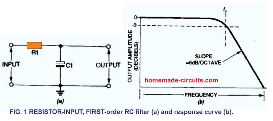
In this post I will comprehensively discuss 10 different types of active filter circuits which can be used for filtering music and audio with the desired levels of bass and treble effects. We also learn about their working, types, characteristics, and practical applications circuits. Contributed By: Ken Madison In audio signal processing circuits, filters are used […]

Filed Under: Audio and Amplifier Projects Tagged With: Active, Diagrams, Explored, Filter, Useful

10 Simple Unijunction Transistor (UJT) Circuit Diagrams Explained

Last Updated on January 17, 2025 by Swagatam 21 Comments

UJT Pulse Generator

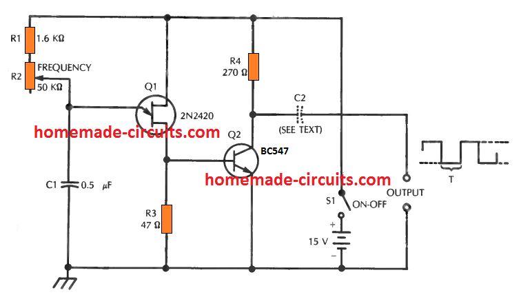
In the earlier post I have explained comprehensively about how a unijunction transistor works, in this post I will elucidate a few interesting application circuits using this amazing device called UJT. The example application circuits using UJT which are explained in the article are: 1) Square Wave Pulse Generator The first design below demonstrates a […]

Filed Under: Oscillator Circuits Tagged With: Diagrams, Explained, Simple, Transistor, UJT, Unijunction

10 Easy Op-amp Oscillator Circuit Diagrams Explained

Last Updated on January 17, 2025 by Swagatam 5 Comments

formula for calculating C1 and L1

In an op amp oscillator circuit, an op amp is configured with a resistor-capacitor feedback loop or a inductor-capacitor feedback loop, which triggers the op amp to go into an oscillating mode, generating a switching ON/OFF pulses from its output pin. The high-gain and wide passband of operational amplifier (op amp) ICs makes it possible […]

Filed Under: Oscillator Circuits Tagged With: Diagrams, Easy, Explained, Oscillator

10 Best Timer Circuit Diagrams using IC 555

Last Updated on January 17, 2025 by Swagatam 89 Comments

plotting of capacitor vs resistor for IC 555 time delay range

The circuits I have explained here are 10 best small timer circuits using the versatile chip IC 555, which generates predetermined time intervals in response to momentary input triggers. The time intervals can be used for keeping a relay controlled load ON or activated for the desired amount of time and an automatic switch OFF […]

Filed Under: Timer and Delay Relay Tagged With: 555, Best, Diagrams, Timer

10 Automatic Emergency Light Circuit Diagrams Explain

Last Updated on January 17, 2025 by Swagatam 280 Comments

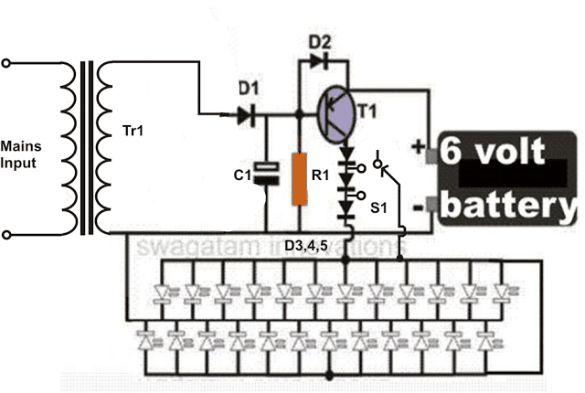
In this article I have explained 10 simple automatic emergency light circuits using high bright LEDs. This circuit can be used during power failures and outdoors where any other source of power might be unavailable. What’s an Emergency Lamp An emergency light is a circuit which automatically switches ON a battery operated lamp as soon […]

Filed Under: Lamps and Lights Tagged With: Automatic, Diagrams, Emergency, Explain, Light

  • « Go to Previous Page
  • Page 1
  • Page 2
  • Page 3
  • Go to Next Page »

Primary Sidebar

circuit simulator image


Subscribe to get New Circuits in your Email


Categories

  • Arduino Projects (95)
  • Audio and Amplifier Projects (133)
  • Automation Projects (18)
  • Automobile Electronics (103)
  • Battery Charger Circuits (87)
  • Datasheets and Components (109)
  • Electronics Theory (149)
  • Energy from Magnets (27)
  • Games and Sports Projects (11)
  • Grid and 3-Phase (20)
  • Health related Projects (27)
  • Home Electrical Circuits (13)
  • Indicator Circuits (16)
  • Inverter Circuits (95)
  • Lamps and Lights (159)
  • Meters and Testers (71)
  • Mini Projects (28)
  • Motor Controller (68)
  • Oscillator Circuits (28)
  • Pets and Pests (15)
  • Power Supply Circuits (91)
  • Remote Control Circuits (50)
  • Renewable Energy (12)
  • Security and Alarm (64)
  • Sensors and Detectors (106)
  • SMPS and Converters (34)
  • Solar Controller Circuits (60)
  • Temperature Controllers (43)
  • Timer and Delay Relay (49)
  • Voltage Control and Protection (42)
  • Water Controller (37)
  • Wireless Circuits (31)


Other Links

  • Privacy Policy
  • Cookie Policy
  • Disclaimer
  • Copyright
  • Videos
  • Sitemap


People also Search

555 Circuits | 741 Circuits | LM324 Circuits | LM338 Circuits | 4017 Circuits | Ultrasonic Projects | SMPS Projects | Christmas Projects | MOSFETs | Radio Circuits | Laser Circuits | PIR Projects |

Social Profiles

  • Twitter
  • YouTube
  • Instagram
  • Pinterest
  • My Facebook-Page
  • Stack Exchange
  • Linkedin


Recent Comments

  • Swagatam on 7 Simple Continuity Tester Circuits Explained
  • Swagatam on Echo Effect Generator Circuit
  • Swagatam on Making a Cell Phone Controlled Remote Bell Circuit
  • Swagatam on Ultrasonic Fuel Level Indicator Circuit
  • Keir Vaughan-Taylor on 7 Simple Continuity Tester Circuits Explained

© 2026 · Swagatam Innovations