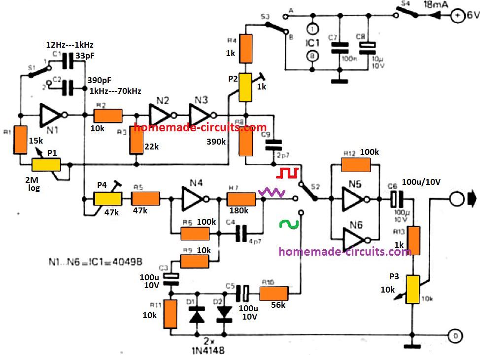
• Skip to main content
  • Skip to primary sidebar

Homemade Circuit Projects

Need circuit help? Post them in the comments! I've answered over 50,000!

Blog | Categories | About | Contact | Calculators-online
You are here: Home / Archives for Diagrams

Diagrams

10 Simple LED Chaser Circuit Diagrams Explained [Knight Rider, Scanner, Reverse-Forward, Cascaded]

Last Updated on January 16, 2026 by Swagatam 170 Comments

knight rider 2

In this article I have explained the construction of 10 interesting yet simple LED chaser circuits, which not only create beautiful running light effect but are also easy to build. We also discuss how to modify these into a design popularly known as “knight rider” chaser circuit. These primarily incorporate LEDs as well as mains […]

Filed Under: Lamps and Lights Tagged With: Chaser, Diagrams, Explained, Knight, LED, Simple

10 Simple FM Transmitter Circuit Diagrams Explained

Last Updated on January 2, 2026 by Swagatam 132 Comments

two transistor FM transmitter

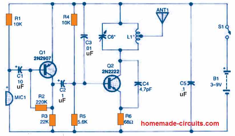
An FM transmitter circuit is a high frequency wireless device which is able to transmit voice signals into atmosphere so that it can be received by a corresponding FM receiver circuit for reproducing the voice signals in a loudspeaker. Here we’ll discuss how to build small FM transmitter circuits using 10 different methods, one that […]

Filed Under: Wireless Circuits Tagged With: Diagrams, Explained, FM, Simple, Transmitter

ACS712 Current Sensor Circuit Diagrams and Datasheet

Last Updated on July 8, 2025 by Swagatam 1 Comment

Here we are going to learn one cool and very important current sensor device which we call ACS712. This small chip that look just like a normal 8-pin IC, is actually able to sense current from any load and give us a proportional analog voltage output which we can easily feed to Arduino or any […]

Filed Under: Sensors and Detectors Tagged With: ACS712, Current, Datasheet, Diagrams, Sensor

110V, 14V, 5V SMPS Circuit – Detailed Diagrams with Illustrations

Last Updated on July 5, 2025 by Swagatam 29 Comments

smps

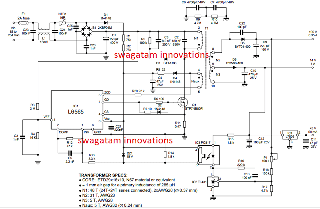
In this post I have explained how to apply the IC L6565 for making a compact multi purpose 110V, 14V, 5V SMPS circuit using minimum number of external components. Implementing quasi-resonant ZVS flyback The IC L6565 from ST Microelectronics is designed as a current-mode primary controller chip, to specifically suit quasi-resonant ZVS flyback converter applications. The […]

Filed Under: SMPS and Converters Tagged With: 110V, 14V, Detailed, Diagrams, Illustrations, SMPS

Simple Boost Converter Circuit Diagrams using Transistors

Last Updated on January 27, 2025 by Swagatam Leave a Comment

boost converter working model

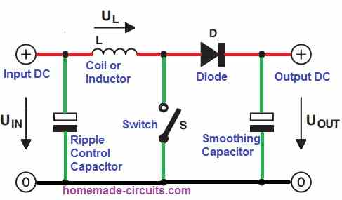
In this post I have explained a few very simple boost converter circuits using only BJTs, or transistors. Let’s learn more. What is a Boost Converter A DC boost converter circuit is designed for stepping-up or boosting a small input voltage levels to a desired higher output voltage level, hence the name “boost” converter. Since […]

Filed Under: Voltage Control and Protection Tagged With: Boost, Converter, Diagrams, Simple, Transistors

0 to 99 Digital Pulse Counter Circuit Diagrams

Last Updated on January 21, 2025 by Swagatam 29 Comments

0to99countercircuit

The proposed 00-99 digital pulse counter circuit becomes very handy in places where you need to keep the people organized in some specified order. Operating details of the digital counter As may be referred the circuit employs the popular 555 IC to genearte the pulse clocks. The pulse counting is done with the help of […]

Filed Under: Meters and Testers Tagged With: Counter, Diagrams, Digital, Pulse

  • Page 1
  • Page 2
  • Page 3
  • Go to Next Page »

Primary Sidebar

circuit simulator image


Subscribe to get New Circuits in your Email


Categories

  • Arduino Projects (95)
  • Audio and Amplifier Projects (133)
  • Automation Projects (18)
  • Automobile Electronics (103)
  • Battery Charger Circuits (87)
  • Datasheets and Components (109)
  • Electronics Theory (149)
  • Energy from Magnets (27)
  • Games and Sports Projects (11)
  • Grid and 3-Phase (20)
  • Health related Projects (27)
  • Home Electrical Circuits (13)
  • Indicator Circuits (16)
  • Inverter Circuits (95)
  • Lamps and Lights (159)
  • Meters and Testers (71)
  • Mini Projects (28)
  • Motor Controller (68)
  • Oscillator Circuits (28)
  • Pets and Pests (15)
  • Power Supply Circuits (91)
  • Remote Control Circuits (50)
  • Renewable Energy (12)
  • Security and Alarm (64)
  • Sensors and Detectors (106)
  • SMPS and Converters (34)
  • Solar Controller Circuits (60)
  • Temperature Controllers (43)
  • Timer and Delay Relay (49)
  • Voltage Control and Protection (42)
  • Water Controller (37)
  • Wireless Circuits (31)


Other Links

  • Privacy Policy
  • Cookie Policy
  • Disclaimer
  • Copyright
  • Videos
  • Sitemap


People also Search

555 Circuits | 741 Circuits | LM324 Circuits | LM338 Circuits | 4017 Circuits | Ultrasonic Projects | SMPS Projects | Christmas Projects | MOSFETs | Radio Circuits | Laser Circuits | PIR Projects |

Social Profiles

  • Twitter
  • YouTube
  • Instagram
  • Pinterest
  • My Facebook-Page
  • Stack Exchange
  • Linkedin


Recent Comments

  • Swagatam on 7 Simple Continuity Tester Circuits Explained
  • Swagatam on Echo Effect Generator Circuit
  • Swagatam on Making a Cell Phone Controlled Remote Bell Circuit
  • Swagatam on Ultrasonic Fuel Level Indicator Circuit
  • Keir Vaughan-Taylor on 7 Simple Continuity Tester Circuits Explained

© 2026 · Swagatam Innovations