This simple yet highly sophisticated, smart LED street light circuit automatically switches ON a street lamp from low brightness to high brightness whenever it detects a moving object underneath it.
This action is initiated only during nighttime, while during daytime the street lamp remains completely shut off.
What this Circuit will do
This advanced automatic street lamp circuit will basically execute the following operations:
- Keep the street lamp completely switched OFF during daytime.
- Automatically switch ON the street lamp in the evening or nighttime at 50% reduced brightness.
- Automatically increase to full brightness whenever a moving object is detected under the lamp.
- Revert to 50% low brightness as soon as the moving object has gone past.
- A delay of 2 second is introduced to avoid rapid switching between low brightness and full brightness.
Main Advantages
The main advantage of this smart street lamp circuit is huge electricity saving and an immense increase in the working efficiency of the street lamp system.
Electricity is saved when the street lamps are automatically switched off during daytime.
Electricity is saved when the street lamps are illuminated at 50% brightness in the absence of a moving vehicle or human under it.
Use of LEDs, further enhances electricity saving and overall efficiency of the lamps.
Being fully autonomous, this street lamp eliminates any human intervention, saving manpower and salaries.
The automatic switch OFF during daytime and the reduced brightness in the idle mode cuts down the stress level and fatigue level on the LEDs increasing its life manyfold.
Circuit Description
As shown in the following image, the proposed smart street lamp circuit employs the RCWL-0516 microwave radar motion sensor module.
I have comprehensively explained about this intelligent motion sensor in the following article:

The complete circuit diagram of this smart street lamp project can be witnessed in the following figure:
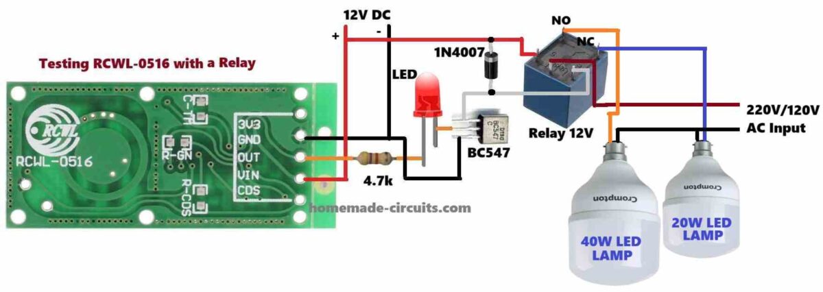
The working of the above circuit can be understood with the following points:
The RCWL-0516 is a microwave radar sensor that uses Doppler radar to detect moving objects.
We use this RCWL-0516 sensor module in our smart street light circuit to detect moving objects beneath it and trigger the brightness level from 50% to 100%.
As soon as a human being, animal, or a vehicle is within 3 meter distance from the lamp post, the RCWL-0516 instantly detects the movement and toggles to full 100% brightness.
In the diagram, we find two LED bulbs, one 40 watt and another 20 watt rated.
At nighttime, when nothing is passing by under the street lamp, the 20 watt bulb remains illuminated via the N/C contacts of the relay.
As soon as a moving target is detected, the RCWL-0516 toggles ON the relay so that its contacts shift from N/C to N/O switching ON the 40 watt bulb and switching OFF the 20 watt bulb.
This results in an increase of brightness from 50% to 100%, enabling the moving target to get optimal illumination on the road.
Once the target has moved away from the lamp post, the RCWL-0516 reverts the relay to its previous N/C position so that the 40 watt lamp is now shut off and the 20 watt lamp is turned ON again.
Daytime Automatic Switch OFF
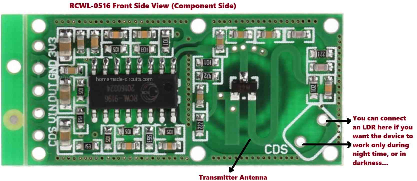
The RCWL-0516 module has an in-built feature which allows it to integrate with an LDR to detect ambient light and remain deactivated during daytime.
Meaning, when there is reasonable amount of ambient light available, the whole street lamp remains deactivated such that the lamps remain completely turned OFF regardless of whether a moving target is present or not.
As soon as the darkness level drops below the set threshold, the RCWL-0516 gets activated enabling the street lamp to become fully functional.
The LDR connection details for the RCWL-0516 module can be found on the opposite side of the module, as indicated in the following figure:
Parts List
- 4.7k 1/4 watt resistor = 1
- Transistor BC547 = 1
- 3.3 V 5 mA LED = 1
- Diode 1N4007 = 1
- 12V, 5-pin Relay = 1
- RCWL-0516 Module = 1
- 12V SMPS Power Supply = 1
- LDR = 1
This concludes our article on smart LED street lamp with motion detector which is highly efficient in terms of saving electricity and manpower.
If you have any further questions or doubts regrading the above project, please do not hesitate to ask them using the below given comment box.
Need Help? Please Leave a Comment! We value your input—Kindly keep it relevant to the above topic!