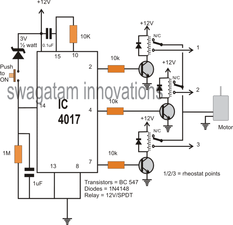
In this post I have explained a simple yet useful 10 step selector switch circuit which can be operated using a singe push-to-ON switch. In the following design the circuit is used as a 3 step, single push motor speed controller unit. The circuit was requested by Mr.Edalcor.
Technical Specifications
hi sir good day to to you, can you please design me a circuit with only one switch (a push button) to control the speed of my dc motor 1st push low, 2nd push medium and 3rd push high the output will go to my 12 volts relay there are 3 relay for low med and high, and the output of my relay will be going to my dc motor with rheostat to control the speed i want to use it for my car air-con. thank you and more power to your blog.
Circuit Diagram
How it Works
The IC 4017 is a johnson decade counter IC with 10 decoded output, designed to produce sequential logic high outputs in response to high/low alternate logic switching at its pin#14.
Here pin#14 of the IC is switched or toggled using a push button switch, which generates the shifting high logic pulses across the output pinouts of the IC starting from pin#3 to pin#11.
However in the shown design since only 3 outputs are used for implementing 3 relay based switches, the IC is resets back to the first pinout as soon as the logic sequence reaches pin#7 of the IC.
If you want to implement a 10 relay operation in that case you can configure the transistor relay driver stages across all the 10 output pins of the IC.
Application Circuit:
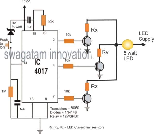
The above concept can be applied as a 3 step LED brightness controller through a single push button, as shown below:
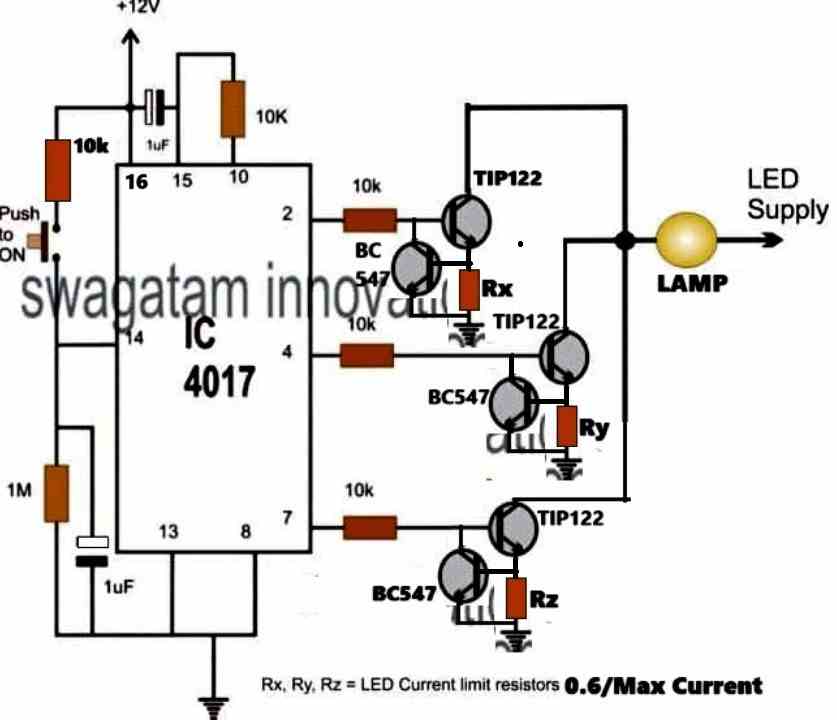
The above design can be further improved, as shown in the following diagram:



Questions & Answers
nice one sir thank you very much i will appreciate your effort of doing this i will try it. My last comment sir, if i push it on the fourth time it will be off?
Yes, the fourth push will reset the circuit to zero or pin#3 which is an unused output, rendering all the relays to off position.
hi sir, again I'm here to bother you. Can i have another request? Can you please design a PWM circuit that fit my A/C blower motor to replace my rotary switch? It is cool if a potentiometer vary the speed of my blower. More power to your blog and thank you.
hi edalcor, why don't you try a dimmer switch for it, you can get pretty cheaply from your local electrical shop?
I have explained it here:
https://www.homemade-circuits.com/2012/04/how-to-make-simplest-triac-flasher.html
i'm sorry sir i forgot to indicate A/C blower motor 12 volts for my car.
do you mean you want to operate a 220v ac motor with a 12V DC input??
no sir the my 12volt evaporator motor in my car air conditioning unit i want to convert the control unit i.e.(fan speed) to PWM instead of the conventional rotary type circuit. thanks for your time.
OK, you can use the following circuit for the application:
https://www.homemade-circuits.com/2012/05/make-this-pwm-based-dc-motor-speed.html
Good One Sir..!!!
Can this concept be used in Home used Mixer-Grinder???
yes surely, but the whole thing with the relays would become too expensive.
ZABARDAST !!!
😀
sir, I want a circuit for control three relay using touch switch(first touch ON and Second is OFF)
You can use the above circuit for the application, just replace the push button terminals with metal pads held close by, …..touching the pads together will enable touch triggering of the relays.
Hai sir: How ten relay circuit maiking tell me plz,,,
Use all the 10 outputs of the IC4017 and connect relays to them in the manner shown above.
For knowing the output pinout sequence order you can refer to the following article:
https://www.homemade-circuits.com/2011/12/how-to-understand-ic-4017-pin-outs.html
great information..
you can use an SPDT switch rated at 20 amps and wire the units through them.
one of the supply input can be wired as common to both the systems, this will engage two wires of the two loads with this common line, next pick the the other supply input and connect it with the center lead of the SPDT switch, after this the remaining two ends of the switch may be terminated with the free supply inputs of the loads individually.
Sir,
I'm here again to disturb you. Please……
If any of the out put terminal left open between two close out put terminal then wheather it will reset at open terminal switching or not ?
With regards,
k.kausik
Kikira, are you referring to the 4017 IC output pins? if yes then the answer is no…it won't reset if any of the output pins is left open….it will reset only if it's connected with pin15 of the IC
Sir,
Have a look on the above circuit and please inform 3v :1/3w zener number and other diodes are 4148 means must be zener but in figure they are simple .
As I have collected all the parts and ready to solder, expecting your final touch as soon as possible.
Thanking you,
K. Kausik
Kaushik, the diodes connected in parallel to the relay coils are all 1N4007.
The one which is marked 3V, 1/4w is the zener diode.
Sir,
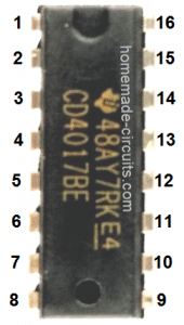
What's the pin no. of ic-4017 just left behind of the pin 15.in the fig.
Thanking you,
K. Kausik
it's pin#16, the supply pin of the IC
Sir,
In this moment I'm under the debris. The above ckt that I made, is working well when I connect a led. But a 12v even if a 6v relay is'nt working.please help.
Egarly waiting for your kind guidance.
With regards,
k.kausik
your relay might not be working due to one of the following reasons:
transistor emitter not connected to the circuit negative line.
transistor pins wrongly connected.
transistor is burnt or faulty.
relay coil resistance is too low for the transistor to make it work.
relay diode is faulty or with wrong polarity…which might eventually burn the transistor
connect a LED with a series 1k resistor parallel to the relay coil, to check the transistor response and whether the transistor is conducting as expected or not.
Sir,
Many many thanks for your quick and valuable advice. But sorry to say none of the relay is responding though leds are.
With regards,
K.kausik
Kaushik, please investigate and check the above mentioned points for finding the exact fault in your circuit.
Sir,
In this late night I have found a solution. I connected the base of a 557 with the collector
of 547 instead of a relay. Then a relay with the557 & a parallel diode 4007. For your kind information now the relay is working.
How is it possible ? Would you kindly explain it…….
Thanking you,
k.kausik
kaushik, it's because your relay has a low coil resistance and requires more current to operate…adding another transistor simply boosts the current and allows the relay to operate.
use 1K at the base of the BC547 and try the previous configuration, without the BC557
or you must use the type of relay which is shown below
1.bp.blogspot.com/-xpR6CBVr5RY/VB7jiU5puOI/AAAAAAAAIRA/gKnCI1xGHFA/s1600/relay%2Bpinout.png
Dear sir,
Good morning and many many thanks for your kind reply. Actually I belong small city of u.p. Though this is the SADAR but there is only one reliable electronic store. The relay that you maintioned is not available here and adding 1k resistor was unsuccessful.
I think it's O.K to add an extra 557 if it is not harmful for the ckt.
With regards and thanks a lot,
K. Kausik
OK kaushik, no problem you may go ahead with it…
alternatively you can also try a BC547 in the Darlington mode, that is by using two BC547 on each channel…this will give you the same results.
Good day sir,
Would you kind help me with the adjust ment to connect the ckt to a 12v/1.5 amp tr.
Thanking U….
K. Kausik
Kaushik, no adjustments would be required in the above circuit.
you just have to make a bridge rectifier and add a filter capacitor to it for converting the trafo secondary AC to DC…this rectified DC can be then connected with the above circuit.
Sir,
Sorry to disturb you. I have already a bridge rec. added with the tr. but 3 ic's has damaged… I think it's due to over current….any how thanks for your kind feedback. I have (already posted on realated ckt.) an another prob. realated with led.. if you kindly take care of it I wil be highly grateful to you….
With regards,
K. Kausik
it may be because of the stepped up voltage after rectification….use a 7812 IC after the trafo DC, this will safeguard the circuit and the IC.
Sir can we use above circuit for time interval switching (interval 3 sec) continuous switching? what is working lifespan of relay? Any other option for relay?
Ashok, yes you can use the circuit for 3 sec continuous switching….relays can have a permanent life and be stress resistant as long as the current through its contacts are much below the rated limit
other option will depend on the load and supply specs
Thanks for your circuit and working it fine, but I want to know will I keep all session in swich on state undil reset the circuit, that means in first push switch on session one and second push switch on session two keep the first session in on state? And what I have to do for this needs, I need 4 steps like these fucrionality
to keep the outputs switched ON you will need to replace the single transistors with a two transistor latch circuit as shown in the following article:
https://www.homemade-circuits.com/2011/12/simple-and-useful-transistor-latch.html
you may need 4 such circuits connected across the 4 outputs of the IC 4017
for resetting you may have to switch OFF the entire circuit and then switch it ON.
thank you for your suggestion and i added two transistors bc547 ,bc557 driven by output0 pin#3 bc557 output to T1 of entire circuit suggested by you. in each session spend 4 transistors. and now it working fine. it made for a led drive dimmer for mirror in my home. thank you again ,
I am glad it worked for you…..but 4 transistors on each channel is not required, the latch circuit uses two just transistors…so it should be two transistors and a relay on each channel??
Really thanking you again for quick response and spending time for my doubts and needs. I did that with total 4 transistors . and tried with 3 but not working. how can send my diagram i modified . ?
OK thanks, just forgot to mention that the outputs of the 4017 should be connected through a diode with the latch circuits, otherwise the latch cannot hold due to the negative trigger by the 4017 while it changes its sequence…
you can use 1N4148 diodes….anode to 4017 IC pins and cathode to the latch trigger inputs.
Ok thank you sir, and I have problem with touch when i extended my lead up to 15cm
Asainar, the above circuit is designed to work with a push switch, a touch sensor might require a different configuration…
Sir I used your touch sensor circuit using 4017 used 2 nos of bc557 in input signal of 4017,
what kind of problem are you facing?
Good useful ckt. you have posted. I would like to know whether the PUSH-TO-ON SWITCH – is it a momentary switch – or push to on and then push to off switch?
Thanks dad,
it's a PUSH-TO-ON SWITCH momentary switch
NAMASTE sir,
Here is a problem….
How can I get out put 4,as the pin #10 is already engage.
Thanking you,
K.Kausik
hello kaushik, which is the pin number after pin#10??
connect that pin with pn#15, then you can use pin#10 for the intended purpose
PRANAM ,SIR,
I have a problem… The circuit is working fine but when I’m trying to control a set of relays as a load (not a motor or bulb etc.)it’s resetting the circuit . Would you kindly help me to resolve the problem…(!!)
Expecting your kind and prompt answer.
Thanking you …
K. Kausik
Hi Kaushik,
That is very strange, because a relay should work without any problems. Anyway do the following things and see if it resolves the issue.
Increase the pin#14 capacitor to 10uF/25V (electrolytic will do). Connect additional 10uF capacitors parallel to each relay coil. Connect a 10uF capacitor directly across pin#16 and ground of the IC.
Also increase the pin#15 capacitor to 1uF
SIR,
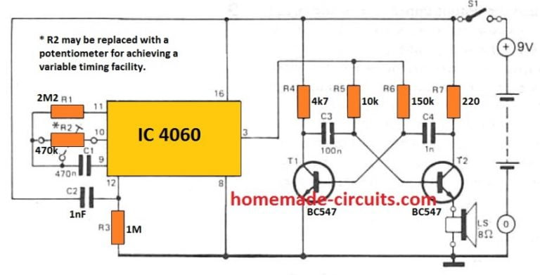
Actually I have coupled a 4060 ic to a 4017 to get 9 out puts for a time period of 1.30 min. each (adding .01 mf capacitor with ic 4060) and trying to control a number of relays with each relay that connected with the output of ic 4017.
Thanking you ….
K. Kausik
With a 4060 clocks the output switching should be absolutely without any issues, I think there might be some problem with your connections or wiring. Are you using a breadboard??
THANK YOU SIR,
The original RELAY connected with ic 4017 output is working fine,when testing with a LED. But after connecting another relay to on &off an circuit. it starts to misbehave.
By the way I’m going to check according to your advice.
Finally thanks a lot……
With a hearty gratitude…….
K. Kausik
Hi Kaushik, do you mean to say you are operating a bigger relay through the smaller relay connected with the IC 4017? In that case did you connect a flyback diode across the bigger relay coil, please make sure you connect a flyback diode across all the relays.
Respected MASTER,
In this dark and rainy night,the roar of the sky, the sound of Crickets and the sweet ripple of the river GOMTI….everything seems just nothing but to praise you. Obviously for the the master of ELECTRONICS.
You are right by more than 100%.
I’ve connected two 10uf cap. across pin#14 & #16 each(omitted 1uf cap. for pin#15)And other 10uf cap. across the relay connected with the O/P of ic 4017. As there is only 7 caps. of 10uf were left I’ve connected 33uf cap. across two pins each.
And it’s working…..really working..
I was stuck by two days with trail and error method by changing ic’s.transistors.re-checking the wiring etc. etc.
But only, your prompt and accurate guidance help me to achieve the goal.
Many many thanks to you…and have a good day …….
K.Kausik
N. B diodes were previously connected with the relays.
I am glad it is working kaushik, let me know if you have further problems.
Good day SIR,
Here is a “LITTLE ” problem…. When I’m switching on the circuit output relay no. 5 and 7 is engaging momentarily.
Would you kindly help me to resolve the problem.
Thanking you ,
K.kausik
Hi Kaushik, increase the value of the capacitor between the positive line and pin#15 to 1uF, presently it is showing as 0.1uF. Electrolyte cap will also do, positive terminal will go to the positive line, and negative to pin#15
Hello sir,
I want to know use of zener diode in above circuit?
Hello Nitin, it ensures that the voltage from the supply reaches pin#14 only after the switch is correctly and fully pressed, and ignores partial or undefined pressing of the button.
Sir I can’t understand what makes it latch in on state, as I think this ic gives only pulse with push button?
Also can it work with 5v ?
Nitin, It is not designed to latch, rather switch on the loads in sequence alternately. Yes it will work with 5V also
Hi
I have a Lighting system DMX controlled by a laptop, with individual keys assigned to different scenes. I would like to automate the system using a decade counter controlling a USB keyboard matrix PCB to switch scenes with a single push button. will it work, can the USB power the decade counter?
Hi, A decade counter will work at 5V, so according to me there shouldn’t be any problems operating it from a USB supply
Thanks for this.
Can I just exchange the relay in the first project with the contacts from the USB PCB or is there more to it. I have already implemented the USB board in a foot switch setup but have to punch individual switches to call up scenes. This will give me far more available scenes and no brainer , just hit one button and there you go.
you can connect any load you wish to have with the relay contacts. Therefore you can surely integrate the USB boards with the relay contacts.
Without the relays I am not sure how you would do it? If you can explain a bit I may try to figure it out?
I have a 10 k between the counter and the cap. Do I need on between the cap and the base
separate 10K capacitors connected from each end of the capacitor to ground, meaning one 10K across positive pin of the cap and ground, another 10K from the negative pin of the cap to ground.
Hi again and thanks
I believe the USB board scans the matrix line and row (square wave I was told) looking for connection. Can a transistor in place of a keyboard contact make this connection or is a relay necessary?
Hi, I would recommend relay contacts for operating the connections. You can use smallest low current relays for this. Transistors can work well for switching supply voltages, but for making connections across two points may they not be too efficient…
I have discovered that my lighting app. changes the scene on the release of the key. Is there a way to make the relay switch on and off after a few milliseconds? Thanks
Yes you can do it by connecting a capacitor, may be a 10uF, across the base/emitter pins of the relay driver transistor. Or you may connect a 220uF/25V directly across the relay coil terminals.
I think I know what this is doing, charge/discharge time of cap, Can you spell it out a little more for both setups, Are these polarized caps, is polarity important.
The capacitor is placed to prevent switch debounce issue, and erratic output sequencing. You can use a polarized capacitor her!!
Just want to make sure I’m on the same page. I want to push the clock in switch on the decade counter, have it turn on the relay and them the relay turns off while the output of the decade counter stays high.
You want to have a momentary ON on the relay, you can have it by putting a capacitor in series with the base of the transistor, negative will go the base, and positive to the resistor. Value can be anywhere between 10uF and 100uF
Excellent, just wanted to make sure I understood the setup.
Glad it helped!!
Another question 🙂 Since I’m going for full 10 count should pin 15 be grounded. if so does it need a resistor to gnd or just strait to ground. In you original schematic there is a cap between 15 and Vcc . Can that be eliminated? Still getting parts together so no circuit progress yet.
Normally the pin#15 can be connected directly to ground but since we need the switch ON auto “reset” function through the indicated capacitor, pin#15 needs to be connected to ground through some resistor, any value between 10K and 1M will do. The capacitor should be around 0.22uF or 1uF max, connected between Vcc and pin#15
Finally got my parts together and bread boarded it up. turns on the relay and works like a stuck key, which I expected, When I put the cap in series with the resistor and base, negative to base, I get nothing. tried a couple of different caps , still not momentary relay action. Any suggestions. I know the basic circuit is working ok as I can see the stuck key stroke on notepad.
If the input signal does not provide a zero logic the capacitor will not discharge. The capacitor must discharge during the off cycles. To solve this issue, you can connect resistors from both the sides of the capacitor to ground. The value can be 10K resistors.
And I hope you have a series resistor with the base of the transistor. All these values are somewhat critical.
Hi could you recommend ic for similar project except for momentary output ( press and hold momentary button led #1 is on as long as button is pressed ,let go of the switch and led one goes off ,press a button again and it’s turning led #2 as long as switch is held. Release the switch and it goes back to switch 1.
Best regards
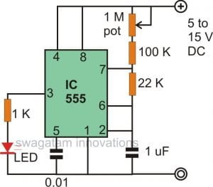
Hi, you can try the following configuration:
Thanx for response. I just tried it on bread bord and it works the way I wanted but there’s a little issue. When I press once led #1 goes on than I release the button it lots up led #2 but than I have to wait for 5-6 seconds for led #1 to light up. Is it possible to make it work constantly?
Best regards
Glad it’s working, but not sure if I understood your question rightly, still you can do a few modifications and check the response. Change the 1M resistor to 10k, remove the zener diode and replace it with a 1N4007 diode (anode will be at the positive supply side, cathode at the switch side)
Ok I got it working. I used 0.1uf caps and switched resistor from pin 7 to pin 4. Now another thing I can’t figure it out is that it doesn’t work on 5v. When I press the button it lits up led#1 but it doesn’t switch to led #2. Any recommendations?
Thanx in advance
You can try replacing the 3V zener with a 1N4007 diode as suggested by me in the previous reply, and check if that helps 5 V operation.
Very nice it works with suggested changes. Thank you for your help.
Best regards!
Thanks, Happy to help!
Hi all!
I would like to light 2 LED lamps that are series at 230v. They turn on with only one switch and I want to switch them on independently or both. how could i change the above scheme to have 2 outputs for 2 relays, and the switch to change it with a pushbutton type, i think.
Condition: 1- A, 2-B, 3-AB, 4-OFF, or 1-AB, 2-A, 3-B, 4-OFF
Thank you very much!
If you put two lamps in series, the brightness will become 50% less when lit together, and when they are lit individually the brightness will become 100%, is that something you wish to have?
If I have 10 output, it will be more simple on operation if it has two switches, 1st for up and 2nd for down. What to modify? Thank you.
up/down sequence may not be possible in this design
High Swagatam,
I want to drive 5m RGB strip LEDs using a 555 timer and a cd4017. I am powering the RGB strip with 12vdc. The 555 pin 3 is connected to pin 14 of the cd4017. Pin 3 of 4017 is connected to a bc548 transistor through a 1k resistor. Pin 2 of 4017 is connected to a bc548 transistor through a 1k resistor. Pin 4 of 4017 is connected to a bc548 transistor through a 1k resistor. Pin 7 of 4017 is connected to Pin 15. Pin 15 is connected to 12v through a 104 capacitor. Pin 15 is connected to ground through a 1M resistor. Each of these transistors is used to drive a 12vdc relay by completing the circuit to ground. Each relay’s normally open contact is connected to either the red or green or blue leg of the RGB strip. The common contact of each relay is connected to ground. 1N4148 diodes are connected across the relay coils. My problem is the relays chatter like crazy when the cd4017 advances. I am posting here as it is the closest circuit type I could find on your site. I am sending you a schematic of my circuit under separate cover as I don’t know how to attach it to this post. Thanks for your help! Happy Holidays!