In this article I have explained a simple walkie talkie circuit that can be easily built by any hobbyist and used for communicating between rooms or floors or simply for having some fun across neighbors and friends. The range of this system is around 30 meters.
A walkie-talkie, also commonly referred to as handheld transceiver is a small, portable hand-held two-way radio transceiver, which enables voice communication across a specified radial distance without using physical wire connections across the devices.
The initial research on walkie talkie concept during the 2nd world war era, has been variously credited to Donald L. Hings, Alfred J. Gross, and engineering experts at Motorola.
Walkie talkies were first supplied for infantry use, and soon it also became indispensable among field artillery and tank units.
Due to their outstanding wireless communication ability, these units quickly became popular among the masses and became a commercial product for the various manufacturers.
Circuit Operation
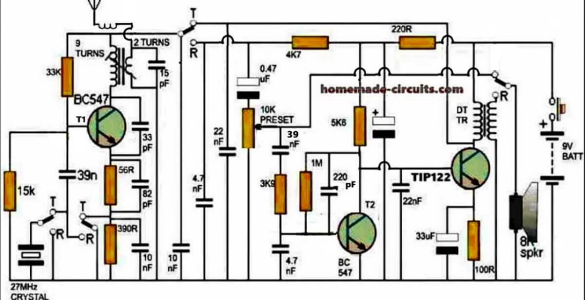
The figure shows a four stage transistorized circuit which behaves both like a transmitter and a receiver unit, making the design very economical and versatile.
An ordinary “4-pole double throw” switch serves the purpose well for transforming the unit either to a transmitter or a receiver while communicating with another identical transmitter/receiver set.
As can be seen in the diagram three transistors are directly coupled for making an audio amplifier stage set to operate at a significantly high gain.
The first transistor functions as a pre-amplifier which pulls the minute voice signals to some higher level and feeds to the next high gain Darlington stage which further amplifies the received audio frequencies and dumps it across the primary of a driver transformer.
How Driver Transformer Works
The driver transformer steps up the level of the signals such that it becomes clearly audible over the connected loudspeaker.
The speaker may be salvaged from an old small transistor radio or from a landline phone (earpice).
The speaker in the shown design is configured in an interesting manner. Depending upon the position of the walkie talkie switch, the speaker works like a sound reproducer when it’s in the receiver mode and like a super dynamic microphone when the switch is toggled in the transmitter mode.
While the speaker is being used as a sound reproducer or simply in the receiver mode, the first transistor acts like a signal receiver, picking up the audio across the 4k7 load resistor through the 0.47uF capacitor.
The signals then has to pass through a connected volume control stage to finally reach the three transistor amplifier stage discussed above.
However while the proposed walkie talkie circuit is flipped in the transmitter mode, the speaker gets rigged right at the input of the amplifier stage such that the spoken voice hits the speaker diaphragm and gets amplified by the same transistor stage.
This amplified voice signal is now applied in the form of supply voltage for the circuit in the transmitter mode. The switch also makes sure that the 27 MHz crystal gets connected with the first stage while the transistor gain is uplifted by eliminating the 390 ohm resistor and using a 59 ohm resistor at the emitter of the transistor.
In the transmitter mode the speaker transformer secondary now has no connection with the voltage step-up function rather simply acts like a series inductor for coupling the output of the audio amplifier with the supply rail and for sending the signal across the winding to the transmitter stage in the form of a fluctuating supply voltage.
As the above signal witnesses a rise and fall in response to the spoken voice, the gain of the first transistor stage is forced to change correspondingly which in turn results in a varying amplitude for the carrier waves transmitted by this stage over the attached antenna.
Thus the spoken voice now gets converted to an amplitude modulated (AM) RF 27MHz signal which may be picked by another identical unit placed in the vicinity for the same reason.
Parts List
All resistors are 1/4 watt 5% CFR
100 ohm - 1
220 ohm - 1
5.6K - 1
4.7K - 1
3.9K - 1
1M - 1
15K - 1
33K - 1
56 ohms - 1
390 ohms - 1
10 k preset - 1
Capacitors Electrolytic
33uF/25V
100uF/25V
Capacitors ceramic disc
0.47uF - 1
22nF -2
220pF- 1
4.7nF - 2
10nF - 2
82pF - 1
33pF - 1
15pF - 1
39nF - 1
Transistors
BC547 - 1
TIP122 - 1
Miscellaneous
Crystal 27MHz - 1
TPTT 3 pole triple throw switch - 1
Audio transformer - 1
small speaker 8 ohm 1 watt - 1
9V battery - 1
Inductor as I have explained below
How to Wind the Antenna Coil
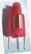
The coil associated with T1 (BC547) collector is the antenna coil. It is constructed over a ready made variable inductor slug (see image below) having an approximate 3mm diameter and around 7 to 10mm height.
The wire used is a 0.3 to 0.5mm super enameled copper.
Start with the primary 9 turns first, directly on this wind the secondary 2 turns.
The coil in series with the antenna is s simple air core coil made by winding 5 turns of 0.3mm with 5mm diameter.
How to Wind the speaker coil
You may use a small audio transformer for the shown speaker transformer, or alternatively build it by winding around 70 turns for the primary (left side), and 500 turns at the secondary (speaker side).
The wire may be a 0.2mm super enameled copper wire wound over a 3 inch long iron screw.
How to Set up the Circuit
After you have built the above explained walkie talkie circuit it's time to check its response by powering it with a 9V PP3 battery.
Initially let the switch contacts be positioned for activating the transmitter stage.
For knowing whether the transmitter is generating the required 27MHz frequencies or not you will first need to make an RF sniffer circuit as explained HERE
Switch ON both the circuits, position the above RF detector circuit about 10 inches away from the walkie talkie antenna, and begin adjusting its variable inductor slug gently using an insulated screw driver which are typically used for adjusting FM radio GANG trimmers.
If every thing's done correctly you'll hopefully see the RF detector LED glowing brightly at some point of the adjustment process.
Seal and glue the variable inductor at this position, and you can assume your walkie talkie to be all set for having some great time with your friends.
However you would need to build another identical set for exchanging the conversations with the other guy, otherwise a single unit wouldn't have much of an importance.
What's the Range of this Walkie Talkie
The range of this 27 MHz walkie Talkie can be around 1 Km, provided the trimmers are correctly adjusted and the antenna is long enough for the wide radial transmission.


Questions & Answers
This what I've been waiting for!!! thank a looooot Swagatam!!!
you are welcome eshkariel.
hi sir,
Thank u so much for this circuit. i m very happy.
My pleasure Abdul…
Sir, I am very happy to seeing this circuit.But sir i want to control reciever and transmeter only one switch.please describe about this.
Pritesh, the four switches which are shown in the diagram are the parts of a single 4PDT switch, meaning you will have only one switch to toggle which will enable all the four contacts to move together inside the switch….
SIR, How to i change its range please describe.
increase the antenna length, it will help to improve the range
sir what is 27MHs crystal.
please Google it online you will get a lot of info regarding its function and appearance.
sir what is the setting frequency for this walkie talkie? can it 88MHz to 108MHz? sorry for my bad english..
jeremiah, it's actually a 27MHz system
…88 to 108 MHz will require a lot of tweaking…not recommended.
Hi. Im very happy with this circuit. Thank you. I do have a question. What is the type or specifications of the transformers used? Please let me know. Thanks.
Hi thanks, the winding data for the transformers are explained in the article, please refer to it.
I do get it now. Thanks a lot bro
Hi. Its me again. Just for clarification, a walkie talkie is a half-duplex wireless intercom right? Thanks.
yes that's right
Hi. I do have a question again. Sorry for having lots of questions. Just due to curiosity.
Which in the circuit acts as the microphone? Because looking in the circuit, there is no such a microphone component. Thank you.
Hi, when the switch is flipped towards Tx the speaker is transformed into a mic, i think i have mentioned this in the article itself
Sir what all modification is to be done in this circuit to increase the range approximately up to 500m
Neeraj, it would be difficult to accommodate more power in this basic design, more complex stages might be required for implementing this.
sir plz tell me about the power of transformer
sir what is the diameter of 3 inch long screw
a 5mm thick core will do
Sir,can u name the antenna
the antenna can be just a meter long wire or if possible a telescopic type of antenna.
Sir,we are unable to get inductor slug ,so please tell how to wind the antenna coil and more over what do you mean by air Cole coil?
Phalguna, the slug type inductor will allow you to adjust and set the frequency easily with a screwdriver, without this it would be extremely difficult and confusing to set the circuit so it's recommended to use a slug type coil only.
air core coil means, a coil built without the need of any core or with an empty core.
what is slug inductor?
please see the second image, it's a coil wound over a plastic former with a threaded screw system at the center for facilitating the screw in and out of the core using a screw driver.
how does RF sniffer circuit can be used for this project?
we are not able to find inductor slug in outside stores
without a slug inductor it would difficult to set the frequency of the unit…..RF sniffers are used for identifying an RF presence……..it won't tell you about the frequency value
Hello! what should be the wattage rating of the 8ohm speaker? Would a regular 10k potentiometer be a viable substitute for the 10k preset? Thanks
Hi, the speaker can be any ordinary 8 ohm small speaker, wattage can be of any value.
yes a pot can be effectively used in place of the shown preset.
thanks for the reply sir! 🙂
would it be possible to add indicator LEDs to the circuit for on/off and transmitter mode without affecting the voltages and currents that much?
I am still unable to find a variable inductor slug 🙁 would it be possible to make one using an iron nail or bolt? Do I still need to insulate the core with plastic?
Thank you so much
Carlos, I can't see any spot in the existing design where an LED could be accommodated without disturbing the circuit's performance, the only way could be to upgrade the changeover switch with an additional pair of contacts, so that this contact can be used for integrating a couple of LEDs for the required indications.
Oh. If that's the case then I won't bother adding the LEDs. I have quite a big problem 🙁 I can't find a BC338 transistor, so far. The stores I've visited only have BC337. Would it be okay to substitue the BC337 to the BC338?
I've checked their datasheets but I still can't decide
Sorry for asking so many questions 🙁 I am planning on making this project for our prototyping class. Our professor asked us to search for a circuit online to build and this really caught my attention. Sorry for the trouble
BC337 can be replaced with BC338, but please note that this circuit requires some good knowledge and skillful hands for the setting up procedure, and this is not for the newcomers, and everything is too critical in the design, even a smallest of faults will stop the circuit from working….try it only if you have built similar circuit in the past and have good experience with RF circuits.
Hello , you already implemented this circuit do that this way , and it worked ?
I have not yet tested it….
hello , I will try to do this project , but I have some doubts .
1 – the variable inductor , I can do it ? I could not find a piece to make it. I have a part for variable inductor but with 6mm diameter , can I use this piece to make it ? The number of turns on it will be the same ?
2 – to the speaker of the transformer, I plan to use a screw with 3 inches. But how should I do? I do the 500 secondary turns of the screw and then put a tape to isolate and make the 70 laps of the primary ?
thank you
1) 6mm will do. and the same coil specs can be used with this diameter too.
2) you'll have to use an audio transformer for the speaker coil….a homemade screw wound coil might not work
Hi Swagatam!!
Thanks for the design, I only have a question, is this circuit transmitting in FM?
Hi Yael, yes it's an FM transmitter/receiver circuit
Hey man thanks for reply and congrats your blog is great..
😀
you are welcome yael!
sir what is the no.of turns for the second transformer ??
It could be around 10:1000 turns, better to go for a readymade audio transformer
Can you please explain how to wind speaker (if you're doing it on your own) show me some pics… it will be more helpful