• Skip to main content
  • Skip to primary sidebar

Homemade Circuit Projects

Need circuit help? Post them in the comments! I've answered over 50,000!

Blog | Categories | About | Hire Me | Contact | Calculators-online
You are here: Home / Wireless Circuits / Simple Walkie Talkie Circuit

Simple Walkie Talkie Circuit

Last Updated on January 1, 2025 by Swagatam 176 Comments

In this article I have explained a simple walkie talkie circuit that can be easily built by any hobbyist and used for communicating between rooms or floors or simply for having some fun across neighbors and friends. The range of this system is around 30 meters.

Table of Contents
  • Circuit Operation
    • How Driver Transformer Works
    • Parts List
    • How to Wind the Antenna Coil
    • How to Wind the speaker coil
    • How to Set up the Circuit
    • What's the Range of this Walkie Talkie

A walkie-talkie, also commonly referred to as handheld transceiver is a small, portable hand-held two-way radio transceiver, which enables voice communication across a specified radial distance without using physical wire connections across the devices.

The initial research on walkie talkie concept during the 2nd world war era, has been variously credited to Donald L. Hings, Alfred J. Gross, and engineering experts at Motorola.

Walkie talkies were first supplied for infantry use, and soon it also became indispensable among field artillery and tank units.

Due to their outstanding wireless communication ability, these units quickly became popular among the masses and became a commercial product for the various manufacturers.

Circuit Operation

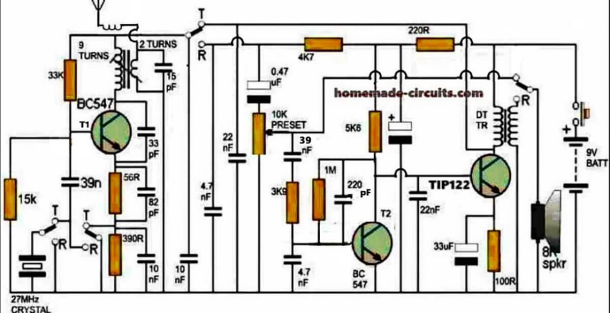
The figure shows a four stage transistorized circuit which behaves both like a transmitter and a receiver unit, making the design very economical and versatile.

An ordinary “4-pole double throw” switch serves the purpose well for transforming the unit either to a transmitter or a receiver while communicating with another identical transmitter/receiver set.

As can be seen in the diagram three transistors are directly coupled for making an audio amplifier stage set to operate at a significantly high gain.

The first transistor functions as a pre-amplifier which pulls the minute voice signals to some higher level and feeds to the next high gain Darlington stage which further amplifies the received audio frequencies and dumps it across the primary of a driver transformer.

How Driver Transformer Works

The driver transformer steps up the level of the signals such that it becomes clearly audible over the connected loudspeaker.

The speaker may be salvaged from an old small transistor radio or from a landline phone (earpice).

The speaker in the shown design is configured in an interesting manner. Depending upon the position of the walkie talkie switch, the speaker works like a sound reproducer when it’s in the receiver mode and like a super dynamic microphone when the switch is toggled in the transmitter mode.

While the speaker is being used as a sound reproducer or simply in the receiver mode, the first transistor acts like a signal receiver, picking up the audio across the 4k7 load resistor through the 0.47uF capacitor.

The signals then has to pass through a connected volume control stage to finally reach the three transistor amplifier stage discussed above.

However while the proposed walkie talkie circuit is flipped in the transmitter mode, the speaker gets rigged right at the input of the amplifier stage such that the spoken voice hits the speaker diaphragm and gets amplified by the same transistor stage.

This amplified voice signal is now applied in the form of supply voltage for the circuit in the transmitter mode. The switch also makes sure that the 27 MHz crystal gets connected with the first stage while the transistor gain is uplifted by eliminating the 390 ohm resistor and using a 59 ohm resistor at the emitter of the transistor.

In the transmitter mode the speaker transformer secondary now has no connection with the voltage step-up function rather simply acts like a series inductor for coupling the output of the audio amplifier with the supply rail and for sending the signal across the winding to the transmitter stage in the form of a fluctuating supply voltage.

As the above signal witnesses a rise and fall in response to the spoken voice, the gain of the first transistor stage is forced to change correspondingly which in turn results in a varying amplitude for the carrier waves transmitted by this stage over the attached antenna.

Thus the spoken voice now gets converted to an amplitude modulated (AM) RF 27MHz signal which may be picked by another identical unit placed in the vicinity for the same reason.
Parts List

All resistors are 1/4 watt 5% CFR

100 ohm - 1
220 ohm - 1
5.6K - 1
4.7K - 1
3.9K - 1
1M - 1
15K - 1
33K - 1
56 ohms - 1
390 ohms - 1
10 k preset - 1

Capacitors Electrolytic

33uF/25V
100uF/25V

Capacitors ceramic disc

0.47uF - 1
22nF -2
220pF- 1
4.7nF - 2
10nF - 2
82pF - 1
33pF - 1
15pF - 1
39nF - 1

Transistors

BC547 - 1
TIP122 - 1

Miscellaneous

Crystal 27MHz - 1

TPTT 3 pole triple throw switch - 1
Audio transformer - 1
small speaker 8 ohm 1 watt - 1
9V battery - 1
Inductor as I have explained below

How to Wind the Antenna Coil

The coil associated with T1 (BC547) collector is the antenna coil. It is constructed over a ready made variable inductor slug (see image below) having an approximate 3mm diameter and around 7 to 10mm height.
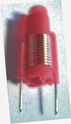
The wire used is a 0.3 to 0.5mm super enameled copper.

Start with the primary 9 turns first, directly on this wind the secondary 2 turns.

The coil in series with the antenna is s simple air core coil made by winding 5 turns of 0.3mm with 5mm diameter.

How to Wind the speaker coil

You may use a small audio transformer for the shown speaker transformer, or alternatively build it by winding around 70 turns for the primary (left side), and 500 turns at the secondary (speaker side).

The wire may be a 0.2mm super enameled copper wire wound over a 3 inch long iron screw.

How to Set up the Circuit

After you have built the above explained walkie talkie circuit it's time to check its response by powering it with a 9V PP3 battery.

Initially let the switch contacts be positioned for activating the transmitter stage.

For knowing whether the transmitter is generating the required 27MHz frequencies or not you will first need to make an RF sniffer circuit as explained HERE

Switch ON both the circuits, position the above RF detector circuit about 10 inches away from the walkie talkie antenna, and begin adjusting its variable inductor slug gently using an insulated screw driver which are typically used for adjusting FM radio GANG trimmers.

If every thing's done correctly you'll hopefully see the RF detector LED glowing brightly at some point of the adjustment process.

Seal and glue the variable inductor at this position, and you can assume your walkie talkie to be all set for having some great time with your friends.

However you would need to build another identical set for exchanging the conversations with the other guy, otherwise a single unit wouldn't have much of an importance.

What's the Range of this Walkie Talkie

The range of this 27 MHz walkie Talkie can be around 1 Km, provided the trimmers are correctly adjusted and the antenna is long enough for the wide radial transmission.
You'll also like:

  • RFID Reader Circuit using Arduino
  • Control a Relay ON OFF Using SIM Card, Mobile Phone, and Arduino
  • optical fiberFiber Optic Circuit – Transmitter and Receiver
  • cellphonefrequencyrangeSimple Cellphone Jammer Circuit

Filed Under: Wireless Circuits Tagged With: Simple, Talkie, Walkie

About Swagatam

I am an electronics engineer and doing practical hands-on work from more than 15 years now. Building real circuits, testing them and also making PCB layouts by myself. I really love doing all these things like inventing something new, designing electronics and also helping other people like hobby guys who want to make their own cool circuits at home.

And that is the main reason why I started this website homemade-circuits.com, to share different types of circuit ideas..

If you are having any kind of doubt or question related to circuits then just write down your question in the comment box below, I am like always checking, so I guarantee I will reply you for sure!


Previous Post: « Water/Coffee Dispenser Motor Circuit
Next Post: How to Make a PWM Controlled Fan Regulator Circuit »

Reader Interactions

Discussion & Solutions

Total Posts: 176 (Older Threads Archive)
Newest Oldest
Tselmeg Enkhbold
April 17, 2026 • 3 months ago #205236

Thank you for sharing your work! I’m planning to build this for a school project, and I was wondering if you’ve personally built and tested this circuit—did it work well for you?

I previously tried making a similar walkie-talkie circuit from a YouTube tutorial, but the audio quality was really poor—I could only hear high-frequency noise and couldn’t understand any speech. So I just wanted to check your experience before I start.

Reply
SwagatamAdmin
April 17, 2026 • 3 months ago #205256

Hi, sorry, no I haven’t tested this practically, however I can assure you that if you build it correctly and stage-wise then this circuit will definitely work.
You can start with the only left side transistor FM circuit and check separately if it sends the signals correctly to a nearby FM radio, once this is confirmed, then you can assume the circuit to be perfectly fine and then you can proceed with the whole setup further…If you have any issues, let me know, I will try to solve it for you…

Reply
Ankur sharma
March 6, 2026 • 4 months ago #202212

I am not able to find TPTT 3 pole triple throw switch in market can i use different switch . when i searched for this ,a big switch is being shown

Reply
SwagatamAdmin
March 6, 2026 • 4 months ago #202221

Please Google with the following phrase: 3-pole triple throw toggle switch
The toggle switch with 9 pins is the one you can try…
These switches are not big…

Reply
Adarsh
March 17, 2025 • 1 year ago #169700

Hello

why does the rf transformer have only two terminals even though circuit shoes 4?

Reply
SwagatamAdmin
March 17, 2025 • 1 year ago #169704

Hi, the image shows an example of the RF coil with an adjustable slug which you can use and modify it with the winding details as given in the article.

Reply
adarsh
March 17, 2025 • 1 year ago #169708

im unable to find the slug on any virtual platform as well as electronics shop sir, any advice?

Reply
SwagatamAdmin
March 18, 2025 • 1 year ago #169736

Then you can ignore the slug type inductor and use a fixed inductor and for tuning the frequency you can use a trimmer capacitor for the 15pF capacitor

Reply
Student
April 30, 2024 • 2 years ago #151877

Hello I try to do same circuit but for 9 turn to 2 turn thing will be variable transformer or variable inductor I couldn’t understand or did you just use the plastic piece to connect the primary and secondary wiring? Because when I look internet about it variable inductor just have 2 pins.

Reply
SwagatamAdmin
April 30, 2024 • 2 years ago #151881

On the plastic former, wind the 9 turns first, then wind the 2 turns over the 9 turns.
To enable firm fixing on the PCB, you can solder the two pins of the plastic former. These two pins can be connected to the 9 turn winding wires.

Reply
Student
April 30, 2024 • 2 years ago #151883

Then what about 2 turn wire because on diagram you use 4 pins instead of 2 pin
Or basically I just gonna do normal transformer with 9 turn primer and 2 turn seconder wiring.
I am sorry if I don’t get it

Reply
SwagatamAdmin
May 1, 2024 • 2 years ago #151889

The two leads of the plastic former is only to provide a firm support to the transformer by soldering the two leads on PCB. So that it allows a comfortable adjustment of the slug. You can keep these two leads blank without any wire connections. Solder the two leads on a blank pads of the PCB. Now you can solder the 9 turn, 2 turns separately on the relevant points of the circuit.

Reply
Gman
March 1, 2023 • 3 years ago #140642

How to make the variable transformer, I’m having trouble understanding on how to make it with the variable inductor coil slug

Reply
SwagatamAdmin
March 1, 2023 • 3 years ago #140646

You can purchase it online:

https://www.google.com/search?q=buy%20variable%20coil%20slug%20screw%20type&tbm=isch&tbs=rimg:CQ15bFxpX3nPYagcvGgxWOFDsgIQCgIIABAAKAE6BAgBEAFAAcACAA&hl=en&sa=X&ved=0CBsQuIIBahcKEwi4gqXOzLr9AhUAAAAAHQAAAAAQCA&biw=1583&bih=757

Reply
David Smith
October 19, 2022 • 4 years ago #134026

Just let know I found the Audio Transformer it is 1K x 8 ohm.
Hard to find to day. Today I can find 1.3K x 8ohm.

The biggest limit to range is the antenna.
The walkie talkie used about 36″ or 1 meter. I did find on high smog from 6 to 7 also also limit the range. After 9 pm and no smog day with give best range and using a longer antenna gave max range.

Dave

Reply
SwagatamAdmin
October 19, 2022 • 4 years ago #134031

Thanks for the update! Glad you found the important parts. Hope you are able to assemble them correctly and get the intended results.

Reply
David Smith
October 9, 2022 • 4 years ago #133851

Check on parts on hand.
The equivalent for the Transistors BC547 and BC338 is a 2N2222. Do you know if 2N2222 will work for both BC547 and BC338?

Are there any photos of past on builds of the walkie talkie?

Thank you

Reply
SwagatamAdmin
October 9, 2022 • 4 years ago #133855

Yes 2N2222 will work.
I don’t have any photos but the above circuit is a tested one.

Reply
David Smith
October 8, 2022 • 4 years ago #133810

Do you now hhe power out put?

Reply
SwagatamAdmin
October 8, 2022 • 4 years ago #133821

The power output is around 80 mW

Reply
David Smith
October 2, 2022 • 4 years ago #133668

A 3P2P Switch can be use
If look schematic on left hand side the crystal do not need to be switched to ground this happens when switch to receiver side. https://www.jameco.com/z/01-690DB-RH-Jameco-Valuepro-3PDT-Pushbutton-Foot-Switch-ON-ON_2181415.html
Can be found on other sites like Amazon and other electronic suppliers

I had this walky talky new back it great.
The down side was the Antenna was to short. If used a 34 feet of wire you could transmit around 5 miles and receive over 15 miles.

If you in mountains use [b]Channel 4 it used by 4×4 clubs. 27.005Mhz or just 27[/b]
It hard to find today any listening to emergency channel 9. I did for 20 years and did here anyone except for someone using the wrong channel.

I would use a voltage regular for 9 volts.
The 9 volt battery did not last long and receiver need adjustment.
Today I planned to 12 volts and a regular to 9 volts

Hope this helps
Dave

Reply
SwagatamAdmin
October 2, 2022 • 4 years ago #133669

I don’t think a 3P2P switch would work, since all the T and the R sides of the switches need to be switched simultaneously. A 4 pole 4 throw switch will be required for this.

Reply
David Smith
October 4, 2022 • 4 years ago #133701

It moving the the resistor R390 and Capacitor 10nf.
Then switch is moved bottom of crystal group. The receiver side is switched to ground.

Reply
SwagatamAdmin
October 4, 2022 • 4 years ago #133702

According the switch symbols in the diagram, the R indicates that the switch needs to switched towards R otherwise the circuit will not not operate in the receiver mode.

Reply
David Smith
October 5, 2022 • 4 years ago #133708

After drawing a schematic out it did work SORRY.

I am using DPDT Relay. I found the push button switch. It is a large and costly switch.

I am hand wiring both Audio transformer and Inductor coil buying off shelf was too costly.

I have all parts for antenna coil and antenna.

I did not find the 330R on the the schematic I think it is the 390R?
{connected to the first stage and the gain of the transistor is increased by removing the 330R and only using a 56R }

Reply
SwagatamAdmin
October 5, 2022 • 4 years ago #133710

Hand winding might not work, you must buy the transformer ready made

Reply
David Smith
October 5, 2022 • 4 years ago #133715

Where is best place to but the audio transformer?
I did not find the 330R on the the schematic I think it is the 390R?

Thank you

Reply
SwagatamAdmin
October 5, 2022 • 4 years ago #133717

You will have to search for the audio transformer online.
There’s no 330R in the schematic or the article…there’s only 390R or 390 Ohms

Reply
David Smith
October 5, 2022 • 4 years ago #133720

Thank you

This is what I found on internet on the
Audio transformer.

{How to Wind the speaker coil
You may use a small audio transformer for the shown speaker transformer, or alternatively build it by winding around 70 turns for the primary (left side), and 500 turns at the secondary (speaker side).}

This walky talky was manufactured in the 1960’s sold by Wards
I have found all other parts on internet and push button by using a low cost relay.

Reply
SwagatamAdmin
October 5, 2022 • 4 years ago #133724

I think before trying this complicated part, you can first build the crystal controlled transmitter section and check whether you can build it successfully or not. Once the transmitter section is confirmed then you can experiment with the audio transformer.

Reply
David Smith
October 5, 2022 • 4 years ago #133730

I do agree with you.
But this walky talky uses the audio transformer as part of transmitter as choke.
I was even think using just choke for just the transmitter witch make it simpler.

Reply
SwagatamAdmin
October 6, 2022 • 4 years ago #133743

Yes, you can try a simple choke and see how it works.

Reply
Jimmy
September 13, 2022 • 4 years ago #133194

I’m new in this, I have difficulty in understanding the three circle and a black line in connecting Crystal,transformer,etc. I can see four times in the schematic, I cannot understand the connection,please help me understand how to connect it, your help will be very much appreciated.

Reply
SwagatamAdmin
September 13, 2022 • 4 years ago #133196

Those are switch symbols, which indicates that all those 4 switches must be operated together, so that all the “T” positions are selected together, or all the “R” positions are selected together while the switch is operated. It can be something like this:

4 pole 4 throw switch

Reply
Jimmy
September 14, 2022 • 4 years ago #133206

I assure you will surely achieve your goal in life for being so kind to me, thanks a million.

Reply
SwagatamAdmin
September 14, 2022 • 4 years ago #133216

You are most welcome!!

Reply
Md. Anisur Rahman
December 21, 2020 • 6 years ago #85527

I need a drone jammer circuit diagram for (2.4-2.5) GHz range 10km and mobile jammer circuit diagram for 1800 MHz and 2100MHz.
Please Help me……….

Reply
SwagatamAdmin
December 22, 2020 • 6 years ago #85538

sorry I don’t have this circuit at this moment…

Reply
Bence
December 9, 2020 • 6 years ago #85185

Some images are missing from this article making it almost impossible to understand. Please reupload the images if you can. Thanks!

Reply
SwagatamAdmin
December 9, 2020 • 6 years ago #85186

I have compressed the image and uploaded it again, please check it now…

Reply
Swagata Acharjee
December 16, 2019 • 7 years ago #73140

Sir, can you tell the value of the inductance then it would be very easy to make the inductor.

Reply
SwagatamAdmin
December 17, 2019 • 7 years ago #73155

Swagata, sorry I do not have the inductance value at this moment, however, if the the indicated number of turns and dimension are implemented correctly it will produce the correct required inductance

Reply
Swagata Acharjee
December 18, 2019 • 7 years ago #73216

ok thank you sir

Reply
Byron carter
December 14, 2019 • 7 years ago #73049

dear swagatam can i use three 3v button cells to get the 9v required for the circuit . i’m making this circuit to put into a star trek original series communicator and this communicator only has 2 tripple a compartment holder built into it . plus can i also use a bought inductor coil for t1 .or is that what the inductor slug is for. plus can i use aluminum foil to wrap around that said communicators antenna grid, or is aluminum foil a bad metal to use, for an antenna. the antenna grid with that communicator i bought is made of plastic.thanks for any help. cordially, Byronc3.

Reply
SwagatamAdmin
December 14, 2019 • 7 years ago #73064

Dear Byron, yes you can use 3 buttons in series to get 9V for the circuit. However the antenna coil must be wound exactly with the same dimension as given in the text. The slug with a iron screw is recommended since the iron screw can be used for tuning the coil precisely. Aluminum foil is actually not necessary anywhere for this design.

Reply
gwapa
July 28, 2018 • 8 years ago #61980

hey sir what simulation software did you use?

Reply
Karthik
July 10, 2018 • 8 years ago #61583

Sir please make a list of all parts I should collect …this is small request ….!! And I didn’t have old telephone speaker so..what I should use in place of it

Reply
SwagatamAdmin
July 10, 2018 • 8 years ago #61604

Hello Karthik, I did not test the design myself so I cannot say anything with assurance, but I’ll try to update the parts list soon.

Reply
sarath
July 19, 2019 • 7 years ago #68574

Hi Swag, is there any way we can order this complete parts kit.

Reply
SwagatamAdmin
July 20, 2019 • 7 years ago #68586

I am sorry Sarath, I don not sell parts, but it may be possible through other online stores. Another good idea would be to purchase a wireless electronic bell and then modify it into a walkie talkie.

Reply
Karthik
July 11, 2018 • 8 years ago #61621

Thanks for reply…..
And please make it soon and give me a idea plzz.

Reply
Solomon
July 5, 2018 • 8 years ago #61439

Hello Sir, This Is A Nice And Interesting Circuit, But Is It Tested And Worked

Reply
SwagatamAdmin
July 5, 2018 • 8 years ago #61443

Thanks solomon, yes it is a tested design, however being a complex RF circuit it is recommended only for those who have thorough knowledge of RF theory and have worked with practical RF designs.

Reply
Chloe Lemaire
June 17, 2018 • 8 years ago #61030

How can I modify this circuit to be wired instead of wireless? Also can it be possible to create a Master Slave circuit consisting of 3 slaves?

Reply
SwagatamAdmin
June 17, 2018 • 8 years ago #61032

The concept explained on the top section of this article: https://www.homemade-circuits.com/spy-bug-circuits/ discusses a wired system, you could refer the first concept and build the basic design from the given information

Reply
Chloe Lemaire
June 17, 2018 • 8 years ago #61034

So I simply remove the circuit after the Transmitter-Receiver Switch and replace it with a wire? Thanks~

Reply
SwagatamAdmin
June 18, 2018 • 8 years ago #61054

actually I was referring to the following article:

https://www.homemade-circuits.com/spy-bug-circuits/

you can use the first circuit, and connect its output with any audio amplifier placed at the receiving end

Reply
Chloe Lemaire
June 18, 2018 • 8 years ago #61064

Lastly, would it be okay if I change the Driver Transformer into a amplifier for the mic/speaker? Since I really like the way speaker converts into a mic.

~BTW, thanks for the link you provided since it helps me a lot considering it only consist of discrete parts.

Reply
SwagatamAdmin
June 19, 2018 • 8 years ago #61077

For the above walkie talkie design, I won’t recommend any changes, it has to be exactly as indicated.
I am glad the linked concept helped you, keep up the good work.

Reply
bambang prayogi
March 12, 2018 • 8 years ago #59042

Is that toy walkie talkie circuit?

Reply
SwagatamAdmin
March 12, 2018 • 8 years ago #59045

Yes it is a toy, with relatively smaller range!

Reply
Coleen
September 27, 2017 • 9 years ago #54289

Hi Sr.! Could you post a video in testing this circuit??

Reply
SwagatamAdmin
September 27, 2017 • 9 years ago #54291

Hi Coleen, sorry that won’t be possible presently…

Reply
coleen
September 29, 2017 • 9 years ago #54360

okay Sr., I understand… I just have another question, Did you try this walkie-talkie circuit by yourself Sir?

Reply
coleen
October 23, 2017 • 9 years ago #55090

Thank you sir 🙂

Reply
SwagatamAdmin
October 23, 2017 • 9 years ago #55093

you are welcome!

Reply
SwagatamAdmin
September 29, 2017 • 9 years ago #54367

I found the schematic inside a readymade walkie talkie package, which was purchased by one of my friends and the model was tested to be perfectly working.

Reply
olupot
August 21, 2017 • 9 years ago #52658

i will be waiting sir i apperciate your efforts

Reply
olupot
August 21, 2017 • 9 years ago #52653

hi sir this circuit looks interesting for its alot of fun but i would want one which transrecieves for both audio and video if possible. that can transmitte and recieve both audio and video from another room thanks

Reply
SwagatamAdmin
August 21, 2017 • 9 years ago #52655

thanks olupot, presently I do not have the requested circuit so can’t say much about its details, if possible I may try to find one and publish here

Reply
Chris Wang
May 15, 2017 • 9 years ago #50516

also what is your reasoning on why a breadboard will not work? what if we do not try to create a case for it?

Reply
SwagatamAdmin
May 16, 2017 • 9 years ago #50529

RF circuits must be tightly built with minimum wiring otherwise it would fail to oscillate and stop working, that's why breadboard cannot be used.
stripboard is OK but the soldering and the connections must be done extremely efficiently.

Reply
Chris Wang
May 13, 2017 • 9 years ago #50466

Hello, have you built and tested this circuit? If so, how well does this work?

Reply
Chris Wang
May 15, 2017 • 9 years ago #50515

what is your opinion on using a stripboard instead?

Reply
SwagatamAdmin
May 15, 2017 • 9 years ago #50507

breadboard will not do…it will need to be built over a neatly designed PCB, and tweaked accurately by an expert having a sound experience with RF circuits

Reply
Chris Wang
May 14, 2017 • 9 years ago #50496

Would you say it is feasible to create this circuit on a breadboard and fit inside a custom 3D printed case? Or would creating one's own PCB be more convenient?

Reply
SwagatamAdmin
May 14, 2017 • 9 years ago #50484

Hello, This circuit was drawn by referring to a commercial unit's PCB, so it is a tested design.

Reply
Jacob Mathew
December 24, 2016 • 10 years ago #47533

also sir, can you please point out where the inductor slug and audio transformer is on the circuit…

Reply
SwagatamAdmin
December 24, 2016 • 10 years ago #47539

inductor with slug is on the left side with BC547 transistor….audio trafo is at the right side

build it only if you are reasonably expert and have previous experience with practical Rf transmitter circuits, otherwise you might fail in getting the results and end up wasting money and time

Reply
Jacob Mathew
December 24, 2016 • 10 years ago #47532

sir and if its it not too much to ask, can you upload all the parts list ?? especially the technical names of the transformers and antennae ??

Reply
Jacob Mathew
December 24, 2016 • 10 years ago #47531

sir, may i know what is 39n ?? there is no 39 nF capacitor that i can find… and how to do this project with a standard double throw switch ??

Reply
SwagatamAdmin
December 24, 2016 • 10 years ago #47540

it is at the base of T1…click the diagram to enlarge.

Reply
SwagatamAdmin
December 24, 2016 • 10 years ago #47538

you can use 33nF instead of two 18nF in parallel.

Reply
Christian Favour
November 13, 2016 • 10 years ago #46420

Sir Pls I Have A Project Work Of Building A Walkie Talkie Of Range 500meter,how Can I Reduce A 2km Walkie Talkie To 500meter Range.Thanks

Reply
SwagatamAdmin
November 13, 2016 • 10 years ago #46426

Christian, you can do it by changing the antenna with a mismatched antenna, or simply reduce the dimension of the antenna.

the other technique is to reduce the supply voltage, or the supply current

Reply
Prajwalchandra r
November 5, 2016 • 10 years ago #46186

Sir can you help me to design with carrier wave of 455khz

Reply
SwagatamAdmin
November 6, 2016 • 10 years ago #46208

you will have to modify the antenna coil and the associated capacitor along with the crystal suitably…

Reply
Esraa Shahin
September 19, 2016 • 10 years ago #44752

its really a well design , but I want to ask you what's the type of antenna did you use here ? and if you know an easy program to simulate it, please ?

Reply
SwagatamAdmin
September 19, 2016 • 10 years ago #44767

thank you, a 6 inches wire will be enough to work like an antenna…

Reply
Akash Hulke
September 5, 2016 • 10 years ago #44244

ok,I will make one more try for that coil, if I find any difficulty, i will ask you.
One little question,
Are the values of components fix or can be change little, like I didn't get 15pF capacitor, they gave me 18pF, is this ok?

Reply
SwagatamAdmin
September 5, 2016 • 10 years ago #44253

slight changes will do which will need to be later on compensated by adjusting the coil dimensions

Reply
Akash Hulke
September 5, 2016 • 10 years ago #44236

Nobody is able to help me in that thing,even my teachers

Reply
SwagatamAdmin
September 5, 2016 • 10 years ago #44238

the design can be modified differently so that it works with a single coil but that will require an expertise and a thorough knwoledge regarding RF transmitter circuits….

anther option would be to buy a ready-made walkie-talkie and then duplicate it by procuring the exact same parts.

Reply
Akash Hulke
September 5, 2016 • 10 years ago #44235

Sir, can you please tell me exactly, what should I do?, this is the only thing now, stopping me in this project.

Reply
Akash Hulke
September 5, 2016 • 10 years ago #44227

Sir, there is only one winding over bobbin, where is the secondary winding?

Reply
SwagatamAdmin
September 5, 2016 • 10 years ago #44230

the picture is only for example purpose it's not the actual image of the coil….the second smaller winding can be wound over the first larger winding

Reply
Akash Hulke
September 4, 2016 • 10 years ago #44217

Sir, can you show me any picture of that winding on screw, at least a drawing or anything, so I can I can get idea of it or please describe it a little more.

Reply
SwagatamAdmin
September 5, 2016 • 10 years ago #44225

Akash, please see the second diagram from top, the coil can be seen wound over a plastic bobbin consisting of a central iron screw, this iron screw can moved up/down using a screw driver

Reply
Akash Hulke
September 4, 2016 • 10 years ago #44206

So,I need to wound 9turns on one end of screw and 2turns on other end. Am I right?
But sir, can I use the wire, which is use in Motor windings?

Sir, we are giving 9V dc supply to the circuit and know that transformers only work on AC, so how audio transformer in the given circuit works.

Reply
SwagatamAdmin
September 4, 2016 • 10 years ago #44215

No, the screw needs to be movable across the coil length so that it can be moved and adjusted up/down with a screw driver….

Motor winding wire will not work,,,,it has to be thicker, around 22SWG

The audio transformer is working with an oscillating DC signal, not with a stable DC.

Reply
Akash Hulke
September 3, 2016 • 10 years ago #44186

Sir, walkie talkie is my engineering project, I will study circuit provided in the link. But my question is,
Can I use IFT in place of that 9turns-2turns transformer.
I tried it and didn't get anything on sniffer circuit.
Can you please tell me how to troubleshoot the circuit I made.

Reply
SwagatamAdmin
September 4, 2016 • 10 years ago #44196

IFT will not work, the core needs to be iron screw type, and the number of turns and diameter must be exactly as mentioned in the diagram.

Reply
Akash Hulke
September 2, 2016 • 10 years ago #44154

Sir,I didn't get 9turns- 2 turns transformer, which is associated with collector of first transistor.
What to do now?, it isn't available in market near me.

Reply
SwagatamAdmin
September 3, 2016 • 10 years ago #44168

Akash, the transmitter coils will need to be built at home…..

if you are not familiar with RF transmitter circuit then you should not try this circuit. you should first practice with smaller circuits as I have explained below

https://www.homemade-circuits.com/2014/08/spy-bug-circuits.html

Reply
SwagatamAdmin
August 29, 2016 • 10 years ago #44009

if you are not familiar with RF transmitter circuit then you should not try this circuit. you should first practice with smaller circuits as I have explained below

https://www.homemade-circuits.com/2014/08/spy-bug-circuits.html

Reply
SwagatamAdmin
August 29, 2016 • 10 years ago #44008

For the antenna coil details please refer to the section
"How to Wind the Antenna Coil"

the speaker transformer is called "audio output transformer", the wattage is not important, It was popularly used in old AM transistor radios near the speaker.

Reply
Akash Hulke
August 28, 2016 • 10 years ago #43990

also sir, if I use 24Mz crystal, then do we need to do changes in sniffer circuit. If yes then which?

Reply
Akash Hulke
August 28, 2016 • 10 years ago #43989

Thank you sir, but what is rating of transformer use near speaker in circuit. And the transformer near antenna 9turns-2turns what is this exactly, what do I need to do exactly here.

Reply
SwagatamAdmin
August 28, 2016 • 10 years ago #43983

You can try a 24MHz, it could just work.

the transformer could be as shown below:

FA8YZ4SFP8NL8P0.LARGE

rest you can search and learn from the internet.

Reply
Demetrio Olarte
August 18, 2016 • 10 years ago #43723

Sir, what color of the audio transformer should be used?

Reply
NIRANT RAUT
August 13, 2016 • 10 years ago #43572

hi sir.. I want to know some things about fm trasmitter

Reply
SwagatamAdmin
August 14, 2016 • 10 years ago #43595

If you have any specific question about it, you can ask… I'll try to answer

Reply
NIRANT RAUT
August 13, 2016 • 10 years ago #43571

i want to make simple walky talky circuit for my project at collge. can u plz help me out for it

Reply
Demetrio Olarte
August 5, 2016 • 10 years ago #43279

how does the speaker acts as a microphone?

Reply
SwagatamAdmin
July 26, 2016 • 10 years ago #42987

walkie taikie is a difficult project you must first know all the basics of RF transmitter receiver concepts

Reply
Unknown
March 23, 2016 • 10 years ago #39952

Thank you sir for this circuit but I have a question if you may
It's about the Antenna Coil ( 0.3 to 0.5mm super enameled copper with primary 9 turns and secondary 2 turns )
what core should I use to wound over ?

Also the coil in series with the antenna ( 5 turns of 0.3mm with 5mm diameter )
what core should I use to wound over also ?
Please explain 🙂 thanks

Reply
SwagatamAdmin
March 24, 2016 • 10 years ago #39966

for the antenna coil use an iron screw as the core which can be moved up down as shown in the second diagram.

for the antenna series coil no core is required

Reply
paul oo
February 17, 2016 • 10 years ago #38836

Do you have EagleCAD or PCB pictures/files to view? I'm curious about the form factor as well (SolidWorks files?)

Reply
Narendra Singh
February 6, 2016 • 10 years ago #38474

Sir, i wanna to get its equipments… Becoz it is so much good for me… So plz sir, tell me briefly about its equipments… Thanks sir

Reply
Alex Malik
December 11, 2015 • 11 years ago #36648

Can you please explain how to wind speaker (if you're doing it on your own) show me some pics… it will be more helpful

Reply
SwagatamAdmin
December 12, 2015 • 11 years ago #36653

sorry, I have never wound a speaker, so have no idea about it.

Reply
Shameeh S
October 30, 2015 • 11 years ago #35333

sir what is the no.of turns for the second transformer ??

Reply
SwagatamAdmin
October 30, 2015 • 11 years ago #35357

It could be around 10:1000 turns, better to go for a readymade audio transformer

Reply
Yael Corona
October 24, 2015 • 11 years ago #35144

Hi Swagatam!!

Thanks for the design, I only have a question, is this circuit transmitting in FM?

Reply
SwagatamAdmin
October 26, 2015 • 11 years ago #35197

you are welcome yael!

Reply
Yael Corona
October 25, 2015 • 11 years ago #35186

Hey man thanks for reply and congrats your blog is great..

😀

Reply
SwagatamAdmin
October 25, 2015 • 11 years ago #35165

Hi Yael, yes it's an FM transmitter/receiver circuit

Reply
joao
September 24, 2015 • 11 years ago #34314

hello , I will try to do this project , but I have some doubts .

1 – the variable inductor , I can do it ? I could not find a piece to make it. I have a part for variable inductor but with 6mm diameter , can I use this piece to make it ? The number of turns on it will be the same ?

2 – to the speaker of the transformer, I plan to use a screw with 3 inches. But how should I do? I do the 500 secondary turns of the screw and then put a tape to isolate and make the 70 laps of the primary ?

thank you

Reply
SwagatamAdmin
September 25, 2015 • 11 years ago #34324

1) 6mm will do. and the same coil specs can be used with this diameter too.

2) you'll have to use an audio transformer for the speaker coil….a homemade screw wound coil might not work

Reply
joao
September 23, 2015 • 11 years ago #34278

Hello , you already implemented this circuit do that this way , and it worked ?

Reply
SwagatamAdmin
September 24, 2015 • 11 years ago #34283

I have not yet tested it….

Reply
Carlos Origenes
April 28, 2015 • 11 years ago #30481

thanks for the reply sir! 🙂
would it be possible to add indicator LEDs to the circuit for on/off and transmitter mode without affecting the voltages and currents that much?
I am still unable to find a variable inductor slug 🙁 would it be possible to make one using an iron nail or bolt? Do I still need to insulate the core with plastic?
Thank you so much

Reply
SwagatamAdmin
April 29, 2015 • 11 years ago #30509

BC337 can be replaced with BC338, but please note that this circuit requires some good knowledge and skillful hands for the setting up procedure, and this is not for the newcomers, and everything is too critical in the design, even a smallest of faults will stop the circuit from working….try it only if you have built similar circuit in the past and have good experience with RF circuits.

Reply
Carlos Origenes
April 29, 2015 • 11 years ago #30502

Oh. If that's the case then I won't bother adding the LEDs. I have quite a big problem 🙁 I can't find a BC338 transistor, so far. The stores I've visited only have BC337. Would it be okay to substitue the BC337 to the BC338?

I've checked their datasheets but I still can't decide

Sorry for asking so many questions 🙁 I am planning on making this project for our prototyping class. Our professor asked us to search for a circuit online to build and this really caught my attention. Sorry for the trouble

Reply
SwagatamAdmin
April 29, 2015 • 11 years ago #30491

Carlos, I can't see any spot in the existing design where an LED could be accommodated without disturbing the circuit's performance, the only way could be to upgrade the changeover switch with an additional pair of contacts, so that this contact can be used for integrating a couple of LEDs for the required indications.

Reply
Carlos Origenes
April 24, 2015 • 11 years ago #30334

Hello! what should be the wattage rating of the 8ohm speaker? Would a regular 10k potentiometer be a viable substitute for the 10k preset? Thanks

Reply
SwagatamAdmin
April 25, 2015 • 11 years ago #30350

Hi, the speaker can be any ordinary 8 ohm small speaker, wattage can be of any value.

yes a pot can be effectively used in place of the shown preset.

Reply
Pabolu Subbu Venkata Sukesh 13BEC1107
April 17, 2015 • 11 years ago #30108

how does RF sniffer circuit can be used for this project?
we are not able to find inductor slug in outside stores

Reply
SwagatamAdmin
April 17, 2015 • 11 years ago #30141

without a slug inductor it would difficult to set the frequency of the unit…..RF sniffers are used for identifying an RF presence……..it won't tell you about the frequency value

Reply
Pabolu Subbu Venkata Sukesh 13BEC1107
April 14, 2015 • 11 years ago #30030

what is slug inductor?

Reply
SwagatamAdmin
April 14, 2015 • 11 years ago #30035

please see the second image, it's a coil wound over a plastic former with a threaded screw system at the center for facilitating the screw in and out of the core using a screw driver.

Reply
Phalguna Pandu
April 1, 2015 • 11 years ago #29673

Sir,we are unable to get inductor slug ,so please tell how to wind the antenna coil and more over what do you mean by air Cole coil?

Reply
SwagatamAdmin
April 2, 2015 • 11 years ago #29686

Phalguna, the slug type inductor will allow you to adjust and set the frequency easily with a screwdriver, without this it would be extremely difficult and confusing to set the circuit so it's recommended to use a slug type coil only.

air core coil means, a coil built without the need of any core or with an empty core.

Reply
Phalguna Pandu
February 15, 2015 • 11 years ago #28797

Sir,can u name the antenna

Reply
SwagatamAdmin
February 16, 2015 • 11 years ago #28819

the antenna can be just a meter long wire or if possible a telescopic type of antenna.

Reply
afnan ahmed
February 10, 2015 • 11 years ago #28703

sir what is the diameter of 3 inch long screw

Reply
SwagatamAdmin
February 10, 2015 • 11 years ago #28712

a 5mm thick core will do

Reply
afnan ahmed
February 10, 2015 • 11 years ago #28702

sir plz tell me about the power of transformer

Reply
Neeraj B A
February 8, 2015 • 11 years ago #28679

Sir what all modification is to be done in this circuit to increase the range approximately up to 500m

Reply
SwagatamAdmin
February 8, 2015 • 11 years ago #28687

Neeraj, it would be difficult to accommodate more power in this basic design, more complex stages might be required for implementing this.

Reply
Mark Aala
October 17, 2014 • 12 years ago #26580

Hi. I do have a question again. Sorry for having lots of questions. Just due to curiosity.

Which in the circuit acts as the microphone? Because looking in the circuit, there is no such a microphone component. Thank you.

Reply
SwagatamAdmin
October 18, 2014 • 12 years ago #26594

Hi, when the switch is flipped towards Tx the speaker is transformed into a mic, i think i have mentioned this in the article itself

Reply
Mark Aala
October 15, 2014 • 12 years ago #26530

Hi. Im very happy with this circuit. Thank you. I do have a question. What is the type or specifications of the transformers used? Please let me know. Thanks.

Reply
SwagatamAdmin
October 16, 2014 • 12 years ago #26555

yes that's right

Reply
Mark Aala
October 16, 2014 • 12 years ago #26548

Hi. Its me again. Just for clarification, a walkie talkie is a half-duplex wireless intercom right? Thanks.

Reply
Mark Aala
October 16, 2014 • 12 years ago #26545

I do get it now. Thanks a lot bro

Reply
SwagatamAdmin
October 16, 2014 • 12 years ago #26543

Hi thanks, the winding data for the transformers are explained in the article, please refer to it.

Reply
Jeremiah Ballos
July 21, 2014 • 12 years ago #24424

sir what is the setting frequency for this walkie talkie? can it 88MHz to 108MHz? sorry for my bad english..

Reply
Unknown
December 3, 2016 • 10 years ago #46981

Sir.. My brother gave me a task to do walkitalki…. Can you please help me sir.. How to do it??

Reply
SwagatamAdmin
July 21, 2014 • 12 years ago #24439

…88 to 108 MHz will require a lot of tweaking…not recommended.

Reply
SwagatamAdmin
July 21, 2014 • 12 years ago #24438

jeremiah, it's actually a 27MHz system

Reply
Pritesh kumar
June 18, 2014 • 12 years ago #23592

sir what is 27MHs crystal.

Reply
SwagatamAdmin
June 19, 2014 • 12 years ago #23608

please Google it online you will get a lot of info regarding its function and appearance.

Reply
Pritesh kumar
June 18, 2014 • 12 years ago #23589

SIR, How to i change its range please describe.

Reply
SwagatamAdmin
June 19, 2014 • 12 years ago #23607

increase the antenna length, it will help to improve the range

Reply
Pritesh kumar
June 18, 2014 • 12 years ago #23588

Sir, I am very happy to seeing this circuit.But sir i want to control reciever and transmeter only one switch.please describe about this.

Reply
SwagatamAdmin
June 19, 2014 • 12 years ago #23606

Pritesh, the four switches which are shown in the diagram are the parts of a single 4PDT switch, meaning you will have only one switch to toggle which will enable all the four contacts to move together inside the switch….

Reply
paul oo
February 17, 2016 • 10 years ago #38834

Thank God.

Reply
ABDUL AZEEZ
June 11, 2014 • 12 years ago #23405

hi sir,

Thank u so much for this circuit. i m very happy.

Reply
SwagatamAdmin
June 12, 2014 • 12 years ago #23414

My pleasure Abdul…

Reply
ashish kher
January 29, 2016 • 10 years ago #38152

any simpler circuit for walkie talkie ?

Reply
SwagatamAdmin
January 30, 2016 • 10 years ago #38173

buy two FM mics with different frequencies and two FM radios, and you can communicate across these units

Reply
eshkariel tapiador
June 11, 2014 • 12 years ago #23404

This what I've been waiting for!!! thank a looooot Swagatam!!!

Reply
SwagatamAdmin
June 12, 2014 • 12 years ago #23413

you are welcome eshkariel.

Reply
Karthik
July 10, 2018 • 8 years ago #61582

Hi .. I didn’t have old telephone speaker ….so what I should do ..what type of speaker I should buy in shop

Reply
sam sharma
July 25, 2021 • 5 years ago #92739

You can use a simple 4ohm 0.5watts speaker for this.

Reply
« Back to Newest Comments

Need Help? Please Leave a Comment! We value your input—Kindly keep it relevant to the above topic! Cancel reply

Your email address will not be published. Required fields are marked *

Primary Sidebar


My Youtube Channel

Circuit Simulator

circuit simulator image


Subscribe to get New Circuits in your Email


Categories

  • Arduino Projects (95)
  • Audio and Amplifier Projects (134)
  • Automation Projects (18)
  • Automobile Electronics (103)
  • Battery Charger Circuits (88)
  • Datasheets and Components (109)
  • Electronics Theory (149)
  • Energy from Magnets and Earth (40)
  • Games and Sports Projects (11)
  • Grid and 3-Phase (20)
  • Health related Projects (27)
  • Home Electrical Circuits (13)
  • Indicator Circuits (16)
  • Inverter Circuits (99)
  • Lamps and Lights (162)
  • Meters and Testers (72)
  • Mini Projects (28)
  • Motor Controller (68)
  • Oscillator Circuits (28)
  • Pets and Pests (15)
  • Power Supply Circuits (91)
  • Remote Control Circuits (50)
  • Security and Alarm (65)
  • Sensors and Detectors (107)
  • SMPS and Converters (45)
  • Solar Controller Circuits (60)
  • Temperature Controllers (43)
  • Timer and Delay Relay (50)
  • Voltage Control and Protection (44)
  • Water Controller (37)
  • Wireless Circuits (31)


Other Links

  • Privacy Policy
  • Cookie Policy
  • Disclaimer
  • Copyright
  • Videos
  • Sitemap

People also Search

555 Circuits | 741 Circuits | LM324 Circuits | LM338 Circuits | 4017 Circuits | Ultrasonic Projects | SMPS Projects | Christmas Projects | MOSFETs | Radio Circuits | Laser Circuits | PIR Projects |


Recent Comments

  • Swagatam on 5 Useful Power Failure Indicator Circuits Explained
  • Swagatam on Simple 20 watt Amplifier Circuits
  • David Lloyd on 5 Useful Power Failure Indicator Circuits Explained
  • Dale on Simple 20 watt Amplifier Circuits
  • Swagatam on Blood Electrification Circuit: Explanation And Working Principle

Social Profiles

  • Twitter
  • YouTube
  • Instagram
  • Pinterest
  • My Facebook-Page
  • Stack Exchange
  • Linkedin

© 2026 · Swagatam Innovations