This transformerless solid-state automatic night lamp operates without using bulky transformer, and automatically switches ON some LEDs during night, and switches them OFF during day.
In this post I have explained how to make a transformerless automatic darkness activated LED lamp circuit, using a couple of transistors and capacitive based power supply, eliminating the use of any bulky transformer.
Compact Transformerless Design
Although the concept may look pretty familiar and common, the main feature of the circuit is its low current consumption and compactness.
The power supply used here is a capacitive type, thus no transformer is incorporated making the circuit very compact and fixable in any small corner of the particular premise.
Why use LEDs
The use of LEDs in place of a filament bulb makes the application very power economic and efficient.
The proposed LED automatic day night lamp switch circuit diagram shows red LED being used, however white LEDs would suit the application better, as that would help illuminate the area better than the red LEDs.
How to Install the LDR
The LDR must be positioned such that the light from the LED does not fall on it, only the ambient light which is to be sensed is required to reach the LDR.
How the Entire Circuit Works
The proposed transformerless automatic day night LED lamp circuit may be understood through the following points:
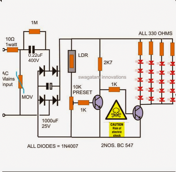
The input 220 V mains suply is applied across the 10 Ohm resistor and the other neutral point.
The 10 Ohms resistor helps to cancel out the initial surge or the voltage rush that might otherwise be potentially harmful to the further stages of the circuit.
The MOV or the varistor placed after the 10 Ohm resistor enhances the protection feature of the unit and grounds all surges that might sneak in after the 10 Ohm resistor.
The capacitor drops the mains voltage current to lower levels and the bridge rectifier made up the four diodes rectify the voltage to DC.
The 1000uF capacitor filters the rectified voltage and the smooth DC is applied to the control circuit consisting the two transistors.
The first transistor is wired up as a comparator, which compares the potential difference across the variable resistor and conducts when the voltage across it rises to saturation levels.
The above rise in the voltage level takes place when the relevant magnitude of light falls on the LDR surface.
Once the resistance of the LDR falls below the set threshold due to higher ambient light, the transistor conducts.
The collector of the above transistor instantly grounds the base of the next transistor and switches it OFF.
The associated LED lights connected to the collector of the second transistor are also immediately switched OFF.
The opposite reaction takes place when the light over the LDR falls below the set threshold, probably during dusk when the sun sets.
The LEDs light up again and remain switched ON until the day beaks and the ambient light over the LDR reaches the set high threshold level.
The following figure shows a simple LED automatic day, night lamp circuit.
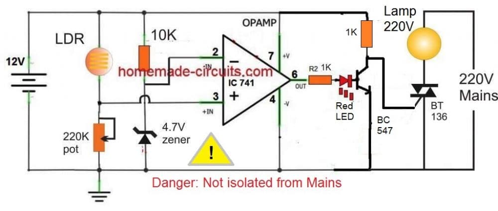
WARNING: THE CIRCUIT IS NOT ISOLATED FROM MAINS AC AND THEREFORE IS LETHAL, IF TOUCHED IN POWERED ON CONDITION WITHOUT A PROPER ENCLOSURE. YOU ARE RECOMMENDED TO EXERCISE EXTREME CAUTION WHILE HANDLING THIS CIRCUIT.
Parts List
- Resistors are 1/4 watt, 55 CFR unless specified.
- 10 Ω 1 watt = 1
- 1 MΩ = 1
- 1 kΩ = 2
- 330 Ω = 4
- 2.7 kΩ = 1
- 10 k preset = 1
- LDR any standard = 1
- Capacitors
- PPC 0.22 µF / 400 V = 1
- Electrolytic 1000 µF / 50 V
- 12 V zener diode 1 watt (to be connected parallel to the above 1000 µF capacitor) = 1
- Diode 1N4007 = 4
- LEDs white high bright 20 mA, 5 mm = 20
- Transistors BC547 = 2
- 300 V MOV (optional) = 1
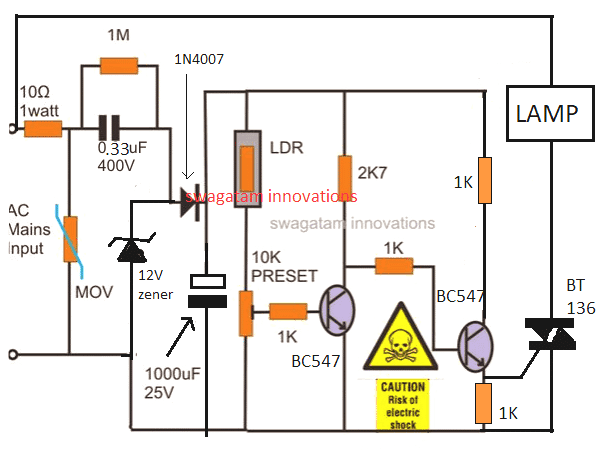
Modifying the Above Design for Activating a 220V Lamp with a Triac
Parts List
- Resistors are 1/4 watt, 55 CFR unless specified.
- 10 Ω 1 watt = 1
- 1 MΩ = 1
- 1 kΩ = 2
- 330 Ω = 4
- 2.7 kΩ = 1
- 10 k preset = 1
- LDR any standard = 1
- Capacitors
- PPC 0.33 µF / 400 V = 1
- Electrolytic 1000 µF / 50 V
- 12 V zener diode 1 watt (to be connected parallel to the above 1000 µF capacitor) = 1
- Diode 1N4007 = 1
- Triac BT136 = 1
- Transistors BC547 = 2
- 300 V MOV (optional) = 1
The above triac based design can be further improved by using an opamp controller for achieving a cleaner automatic switching action of the lamp during darkness, as shown below:


Comments
Sir mene ye circuit banaya hay laikin 2.7k resistor bohot hot ho raha hay or smell bhi aarahi hay koi problem tu nahi hay?
Syed, which capacitor did you use at the input?
0.22uF would not burn a 2k7 resistor
try using a 15V 1 watt zener across the bridge output
I've check it again, I've missed to place the 1K resistor on the base, And it work fine just getting warm. Thank you for the circuits.
OK great, thanks for updating the info…
I'made the circuit with several improvement. Am using 105uf mains dropper cap. I add 39V MoV between + and – of the bridge.am using 2caps (1,8uf & 2.2uf all 400V)at the same point of MOV. Am using 2 string with 12LED on each.
My question is the LED gets extremely hot when the day come and mulfunctioning occure, why is that happen..? Any suggestion to repair this.? Thank you..
How can the LEDs get hot during day, because during day time current is supposed to drop for the LEDs….do you mean to say the transistor which is driving the LEDs gets hot??
Please clarify?
Sir mov meri taraf available nahi hay is ki jaga koi or component laga saktay hain like zener diode?
Syed, actually MOVs are identified with their max voltage rating while NTCS are specified with resistance value at normal temperature.
In your case a 5 ohm NTC would be fine.
you can use the one that's explained in the following article:
https://www.homemade-circuits.com/2013/02/using-ntc-resistor-as-surge-suppressor.html
Sir 300v k ntc ka koi code hay?
Thanks Sir
yes that's right, no need of putting both.
Sir jb ntc laga dain ge tu mov ki zarurat nahi hay?
you can use a 300V NTC and replace it with the 10 ohm/1watt resistor
What is the value of ntc? Where i can place ntc in diagram?
you can use an NTC or you can use a coil wound over an iron bolt or screw using any thin (0.3mm) copper wire with 200 turns, and insert this coil between the bridge positive and the LDR.
the wire must be a super enameled type copper wire which are used in transformers.
Sir what is 10 k present? And what is 2k7?
it's a 10k preset or 10k variable resistor.
2k7 is 2.7k resistor
Sir mov ki koi value hoti hay kia ya 1 hi value ka hota hay?
it's identified by its clamping voltage value, or the voltage at which it is supposed to activate and conduct
for 220V mains it should be around 300V
the capacitor value is not important, anything above 1000uF will do the job…but higher values will give better ripple correction.
0.22uF ill work only with one channel of LEDs, but for 4 channels as give in the diagram , you might need 1uF/400V
more info can be studied here:
https://www.homemade-circuits.com/2015/01/calculating-capacitor-current-in.html
Sir, what if i want to use 12v battery or 12v ac/dc adapter what should i remove? and how many LED arrays can i add?
Alex, you can use the same circuit, just use three LEDs on each string and a 150 ohm resistor.
Dear Sir, I'm a computer engg and interested in Electronic circuits. Im refering your blogs, thanks for such elaborated comments. You are explaining and teaching us.
From your comment, i have changed the Capacitors 25V1000uF to 50v1000uF & 105/400V to 474/400V.
Could you pls tell "the watts of 1M Resistor", "whats 2K7 Resistor", "10K preset".
Awaiting your feedback, thanks.
Dear Anish,
All resistors are 1/4 watt rated, preset is normal type.
hi wat is the watts of resistors
kindly help
dr yudhvir singh
yudhvir0039@gmail.com
all are 1/4 watt rated except the 10 ohms, please use a 0.47/400V instead of the shown105/400V at the input for a reduced safe current
Hi,
I built the circuit and it works,
however I think I have something wrong, the 25v cap gets very hot and if i measure the voltage out of the bridge rectifier it's 46V, whilst the leds are off, when when the leds are on measures 21 V should this be changed to at least a 50V cap?
thanks, yes that's why a 0.22uF is used in the present design…
capacitive power supplies become very efficient if the load voltage spec is selected to match the output of the power supply
Here is an interesting scenario.
Suppose 1uF is used for the current-limiting capacitor, with 220V mains, the maximum current the circuit can supply is roughly 69mA. There are four LED strings, each connected to a 330Ω resistor. As measured by Riccardo, the voltage drop is 21V. Ignoring the voltage drop across the rectifier, the voltage at the input side or across the 1uF capacitor is (220V – 21V) = 199V. This means the current that can be supplied by the circuit when the LEDs are ON has been reduced to 199V / 3.183kΩ (reactance of the 1uF capacitance) = 62.52mA; meaning 15.63mA will flow through each LED string. Voltage drop across the 330Ω resistor is I x R = 5.16V, plus the 15V across the 5 LEDs, the total voltage drop is 20-21V that matches the measurement of Riccardo. Ignoring the minute power consumed by the transistor portion, total power consumption by the four LED strings = (21 x 62.52)mW = 1.31W.
When the LEDs are in OFF state, the measurement from Riccardo is 46V. That means the current supplied by the circuit is (220V – 46V) / 3.183kΩ = 54.67mA. This translates into a power consumption of (46 x 54.67)mW = 2.51W.
If Riccardo's measurements and my calculations are both correct, that means the power consumed when the LEDs are OFF is actually twice as much as when they are ON.
The purpose of an automatic night-light is to save power in addition to its automatic feature. Using a capacitive transformerless power supply does not gain both edges.
Hi, yes that's right use a 50V rated capacitor and also try reducing the 105/400V cap to 474/400V for keeping things cooler and safer
can i use 8 1-watt led in this circuit
No, 1 watt leds will not illuminate brightly.
sorry sir! I don't understand about 2 transistor? can you tell me about the value or name of them?
pousia, please explain your requirement more elaborately, what do you want the alarm to warn you about?
sir can i implement automatic alarm in this circuit???? if can please help me…
sir can we implement automatic alarm in this circuit?if can please help me
those are BC547
What is mov spare this circuit
it's a current surge suppressor.