This step down buck converter will convert a 220V AC input from mains supply to 5V or 12V or 24V DC with 90% efficiency.
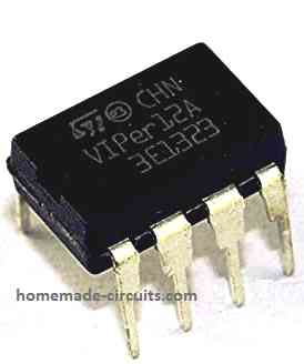
The proposed buck converter is an SMPS circuit using the IC VIPer12A from STMicroelectronics.
The circuit uses negligible number of external components yet is able to operate directly from mains AC input.
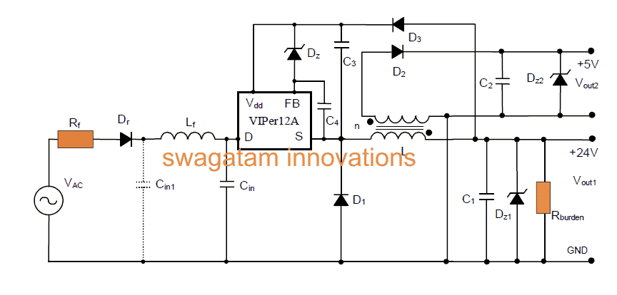
The Buck Converter Design
Looking at the given circuit diagram we see that the input stage incorporates a surge limiting resistor which quite acts like a fuse, a diode for rectifying the AC, and an LC filter network for further filtration of the DC riples.
The LC filter employed here ensures better DC stabilization and enhanced EMI response.
The capacitor Cin1 may be introduced for further reinforcing the EMI functionality.
The IC VIPer12A becomes the main PWM processor device which single handedly performs the entire buck conversion in the circuit.
Main Features
The main specifications of the configuration may be understood as follows:
- AC input voltage Vinac 80 - 285Vac
- Output current Iout 30mA
- Output current Iout 250mA
- Output voltage Vout1 +24±10%V
- Output voltage Vout2 +5V±5%
- Switching frequency 60 kHz
- Output Power ~ 1W
How it Works
The circuit facilitates two outputs, rhe 24V output is achieved through a buck converter configuration while the 5V output via fly back mode.
The feedback voltage to the IC is acquired from Vout1 for the required regulation of the output, this supply is also applied to the IC Vdd pin.
The above wiring becomes possible by using a single high voltage diode and just one capacitor, to be precise D1 and C3, making the connections and costing much simpler.
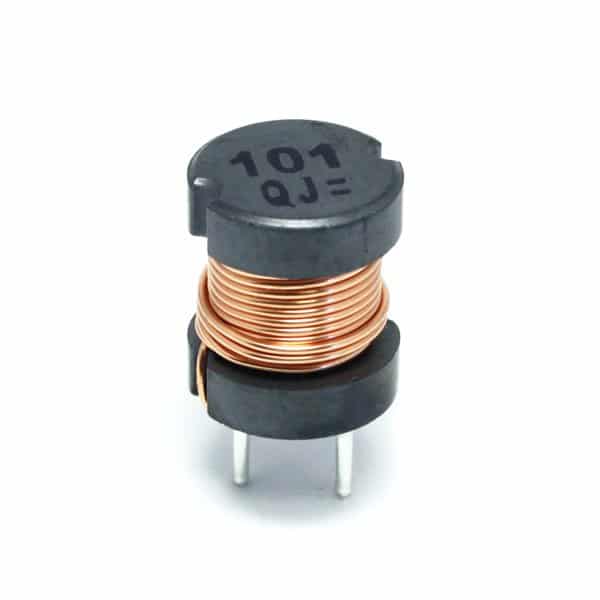
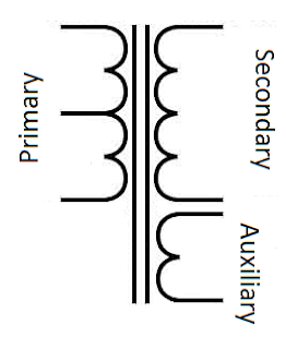
The employed inductor L consists of two windings which are coupled across with each other over a common ferrite core.
The winding are done through appropriate turn ratios, where N1 = 200 turns and N2 = 60 turns. Both these are wound over a PANASONIC ELC10D152E ferrite core material.
Zener diodes z1 and z2 are installed in order to safeguard the outputs against over voltages.
A dummy load resistor is fixed across Vout1 so that appropriate regulation can be executed over both the outputs during open load situations.
Though the addition of the above resistor affects the efficiency a bit, it superbly improves voltage regulation response of the circuit.
The rectifier diodes fixed at the output are fast response fast recovery types. D1 is a high voltage diode as it might be subjected to high reverse voltages delivered by the DC bus voltage...... D2 is a normal diode.
Parts List for the proposed simple SMPS buck converter circuit:
- Rr = 10W 1/2W
- Rf = 10KW 1/4W
- R(load) = 4.7kW 1/4W
- Cin = 4.7 μF, 450V Electrolytic Capacitor
- C1 = 33 μF, 50V Electrolytic Capacitor
- C2 = 100 μF, 16V Electrolytic Capacitor
- C3 = 1 μF, 25V Electrolytic Capacitor
- C4 = 22 nF Ceramic capacitor
- Dr = Diode 1N4007
- D1 = Diode BA159 (fast)
- D2 = Diode 1N4148 (fast)
- D3 = Diode 1N4004
- Dz = 22V Zener
- Dz1 = 27V Zener
- Dz2 = 5.6V Zener
- L 1 = 0.5 mH
- Lf = 470 μH Inductor
- IC1 = STMicroelectronics VIPer12ADIP
PCB Design and Component Layout of the above explained SMPS buck converter circuit using IC VIPer12A
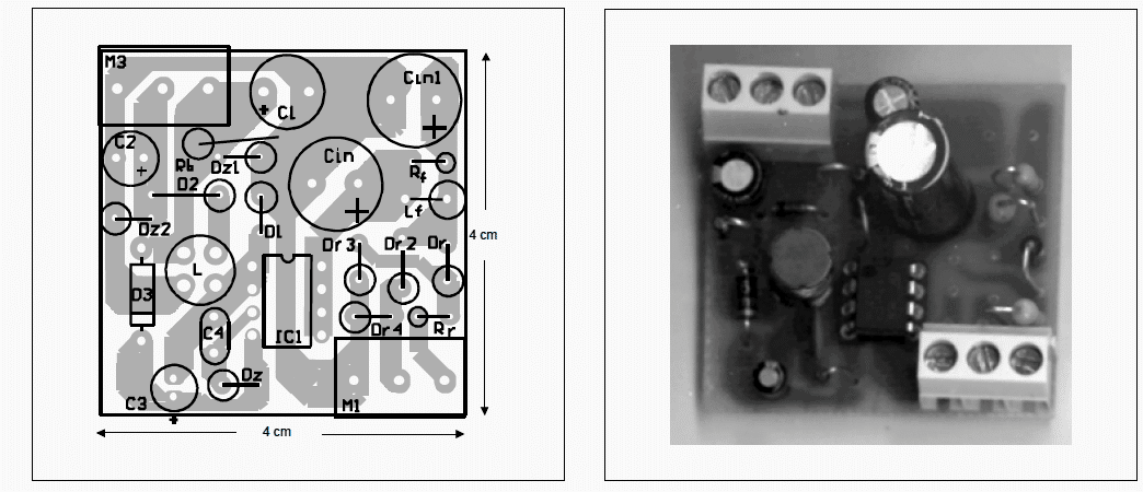
Complete Article can be found here


Comments
If I want it to send a voltage of 75 to 80v with a current of at least 40mA, what modification could be made to the circuit?
I don’t think 75V is possible using the above explained concept…
how to use a MOSFET to gain more current >2-2.5A output from LM317 .
Will appreciate any help and cicuit design
the oupt voltage +5v
In that case why not use an LM338? No need of any MOSFET, it will provide 5 amp current from 3V onwards. Plus it is fully protected internally against heat, over current, over load, which the MOSFET cannot provide…
Hi Thanks for the tip but will this regulator LM338 be ‘low noise” .?
I intend to use it as a filamenrt supply for a power triode 845 . It needs DC 10v 3A supply . I read that buck converters were great for that because of the high operating frequency is above the the audio spectrum and so no “50Hz hum of the tube. Not sure it cab withsatand a 3A current?
It’s my pleasure! To reduce or eliminate noise, you can put capacitors at the input and output terminals of the IC, that will take care of the noise issue. Even in a buck converter, possibly a 50Hz hum can easily ride over the high frequency content. In order to 100% eliminate the hum you can consider using a notch filter, such as this:
https://www.homemade-circuits.com/simple-hum-filter-circuit-for-amplifiers/
Sir, I need DC 96v to 12v not Ac, please can I get simpler version, thanks
The following circuit can be used with DC also….for DC you can remove the input coil and the capacitors.
https://www.homemade-circuits.com/simple-220v-smps-buck-converter-circuit/
For simple circuit you can make the following:
https://www.homemade-circuits.com/wp-content/uploads/2021/11/single-transistor-voltage-regulator.jpg
replace the zener with 12V zener and the resistor with 10k 2 watt. the transistor will get immensely hot.
here the transformer you have used “PANASONIC ELC10D152E” has 2 pins then how come it has primary and secondary windings in it?
I only wanted to show the type of ferrite core required for the project. The two secondary wires can be left hanging after properly gluing them with the winding, and then the ends can be soldered to the PCB.
pls is it possible to use a voltage regulator as replacement for output inductor if you can’t find an inductor?thanks
A Buck converter can never work without an inductor, so it cannot be replaced by anything else. The above inductor is very easy to build.
Thanks for your reply.Please i would appreciate any suggestions on how i can go about buiding my inductors personally as it is not easily available in my area..Much appreciated.
The coil are already given in the article. The primary is 200 turns, and secondary is 60 turns.
iam an electronics engr right from NIGERIA the aboved diagram the viper had no starting position pls send it eill help so much thanks
why do we need Cin1?
To create an LC pi filter for improved filtration….
Sorry to ask this but I’m very beginner.
I would like to ks.ow about that inductor how to connect like a transformer which has 4 pins.
because I look in the datasheet that Panasonic inductor has only 2 pins.
Hello, the 4 pin inductor shown in the diagram does not need to have pins, you can use the wire ends of the winding directly on the PCB, just make sure the winding are firmly secured with insulation tape.
How can i find the text file of VIPer12A ?
Hello Sir,
Kindly suggest an application for winding Ferite Core Inductors using EE cores and Dog Bone cores.
Thanks in Advance.
Hi Akash, the calculations can be found here:
https://www.homemade-circuits.com/how-to-design-and-calculate-ferrite-core-transformers-for-inverters/
I have no idea what a dog bone core is?
how to make only one 12V 1A(approx) usinh this ic.
try replacing the IC with viper22A, as used in this design
https://www.homemade-circuits.com/how-to-make-simple-12-v-1-amp-switch/
hi what modification need in above circuit to get 4.2V 2Amp as out put from 230V ac
You can slightly adjust the number of turns on the side of the inductor which is associated with the 5V output….or simply add a 1N4007 diode in series with the 5V output to get the required 4.2V approximately.
is it related to inductor wire guage
it is related to number of turns not gauge, gauge is related to current…
yes sir for 2 Amp current i need to change winding guage i think and for voltage as you said i use diode
sorry, I just forgot to tell you that 2 amp may not be possible with this circuit, the maximum current is 250mA for this design
you can try this instead
https://www.homemade-circuits.com/12v-2-amp-smps-circuit/
Hello Sir,
Possible to design viper50 or viper 100. smps circuits. output is dual 15V @2amp. i need to power-up my preamp mixer.
thanks
Hello Odie, the part values for the Viper100 circuit has not been properly detailed in the datasheet of the IC, I will have to study and then estimate the part values, so that might take some time.
in the meantime you could try the following design instead
https://www.homemade-circuits.com/2014/06/smps-2-x-50v-350w-circuit-for-audio.html
the output winding turns could appropriately reduced for getting the required 15V
please remove this circuit as beginners may think it is working.
Ofcourse it is working.
it is a wonderful circuit, I have tested it myself
hello sir, currently i am trying to get 13V 4Amp DC from 19V 4.5Amp DC input….i tried voltage divider cct but at the end found out buck converter to be the possible solution…….
I am avoiding LM317 with resistor network…..as i fear its O/P may vary if resistor got burned ………..
could u plz suggest the buck converter design ……??
is cct in this article could be modified to get 13V O/P……..??
Hello Muhammad,
You can try the following circuit:
https://www.homemade-circuits.com/2015/05/5v-pwm-solar-battery-charger-circuit.html
you can alter R8, R9 values for getting the desired output
…for 4amp load LM317 will not work, you can try LM338 instead.
So nice of you Sir, I will check feasibility of both and will be back with results soon………:))
Hello Sir,i am making a buck converter in analog domain without using any IC's.I have used an astable multivibrator for generating the squarewave(350khz) required for switching the Mosfet on and off.The problem was with the gate driver circuit required for mosfet.i used a complementary symmetry push pull amplifier(using BJT) as the Gate Driver.But this driver circuit was not switching the mosfet ON and OFF.Instead it keep the Mosfet ON continuously.Suggest me ways to overcome it and also give me advice on how to provide automatic feedback for keeping the output voltage constant at 9v irrespective of Input voltage Variation(Line Regulation) and Load Change(Load Regulation).Please Do help me out
Hello Sam, without seeing the design it would be difficult for me to assess the fault and suggest an appropriate solution, if possible show me the schematic by uploading the image on Google drive or any other free image hosting site and provide the link to me….
hello,
can you please help me how to current increase without changing voltage
thanks in advance
current cannot be increased, 50mA is the maximum limit of the mentioned IC.
you may have to change the IC with a VIPer22a for getting 250mA…
more info is furnished here:
http://www.st.com/web/en/resource/technical/document/application_note/CD00004329.pdf
Hello
can you wright an explanation how this circuits start to work ( IC VIPer12A )
hello,
you can refer to the datasheet of the IC for the details.
hello,
can you please help me modify this circuit to get the output voltage at 110v , including the ferrite core transformer design if possible
thanks in advance
The circuit would be basically the same as suggested in my previous email since the input is 220V.
However the output frequency will be equal to the input mosfet frequency at around 60kHz which unfortunately cannot be changed to 1000Hz. you may have to employ another stage at the 110V output stage of the circuit for enforcing it.
thanks a lot for the input,
what i am actually trying is to make an inverter which has :-
input:220v ac 50Hz
output:110V ac 800-1000Hz
right now i am trying a half bridge inverter with mosfets and capacitor divider.
can u suggest some good circuits?
thanks in advance
no, the above circuit cannot be modified for 110V, you can try it in the following circuit:
3.bp.blogspot.com/-Jbp0LrP-PlU/UxWFwYeF2ZI/AAAAAAAAGaM/kRgOicbzIaE/s1600/12v+5+amp+transformerless+battery+charger+circuit.png
the output winding may be made by winding 50 turns and the zener replaced by a 140V zener
what i meant was to obtain 110V output instead of 12V from 220V mains input
hello, the above circuit is designed to work right from 85V to 285V, so the same design could be used for 110V too.