In this article I have explained how to make a simple RF remote control circuit using ready-made RF 433MHz and 315MHZ RF modules, and without incorporating microcontroler ICs.
With the easy availability of RF modules today making an RF remote control has become a childs play.
It's all about procuring the RF modules ready made from the market by spending a few bucks and configuring them together for the intended results.
Here I'll show you how to make an approximately 100 meter range RF remote control circuit using RF modules, without the help of any microcontroller stage.
To begin the assembly you will have to procure the following readymade RF modules and the respective encoder and decoder chips, for the present project we use the HOLTEKs modules:
RF 433Mhz Transmitter/Receiver Modules
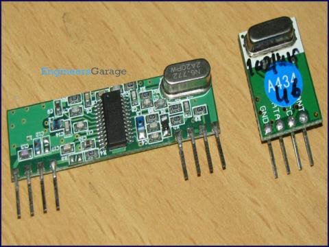
The following picture shows the Rx (left) and the Tx (right) Modules.
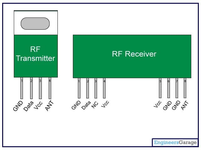
The following figure shows the pinout details of the above modules.
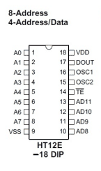
Encoder IC = HT12E
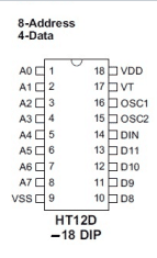
Decoder IC = HT12D
The above encoder and decoder ICs do the jobs exactly as per their assigned names that is encode and decode the bit information for enabling easy interfacing with analogue circuits.
After you have procured the above components it's time to put them together.
Assembling the Modules
Configure the transmitter circuit by assembling the Tx (Transmitter) Module with the Encoder IC as given in the following circuit:
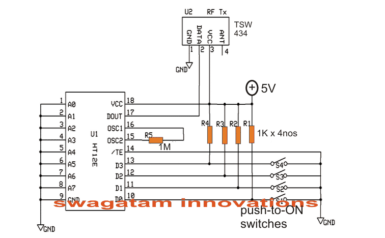
Next, assemble the Rx (Receiver) module with the decoder IC, as per the following diagram:
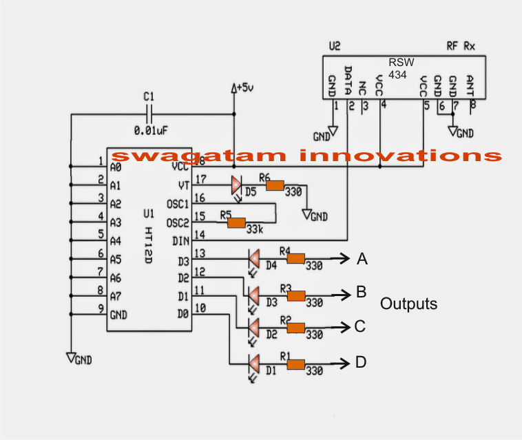
In the above Rx (receiver) circuit we can see that four of its outputs are terminated through LEDs at the points A.B,C,D and another output which is terminated via the VT pinout of the IC.
The four outputs A,B,C,D become high and latched in response to the pressing of the four push buttons shown in the Tx transmitter) circuit.
Pin13 switch of Tx influences the Pin13 output of the Rx and so on....
Suppose when output "A" of the Rx module is activated by the relevant switch of the Tx, it gets latched and this latch breaks only on activating any of the other outputs.
Thus the latch breaks only when a different subsequent output is rendered high through the Tx relevant push buttons.
The output from pin VT "blinks" momentarily every time one of the outputs A,B,C,D get activated. Meaning VT output can be used in case a flip flop is required to be operated.
The above can be very easily interfaced with a relay driver stage for operating any equipment such as a remote bell, lights, fans, inverters, automatic gates, locks, RC models etc.
How to Connect the Address Pins
The pinouts A0-----A7 of the Rx, Tx modules are very interesting. Here we can see them all grounded which creates an impression that these are of no use and are simply terminated to ground.
However these pinouts enable a very useful feature.
These address pinouts can be used for rendering a particular Rx, Tx pair uniquely.
It's simple, let's say for pairing the above modules we ensured that the address pins are identically configured.
Alternatively we could make the above pair unique let's say by opening A0 for both the modules. This will make the pair respond only with each other and never with any different module.
Similarly if you have more number of such pairs and want to make unique pairs out of them, just assign the pairs in the explained manner. You can do this by either connecting the address pins to ground or by keeping them open.
It means by rendering different configurations to the relevant address pinouts between A0 and A7 we can create a huge number of unique combinations.
The range of the above explained RF module is around 100 to 150 meters.
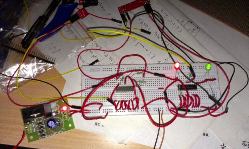
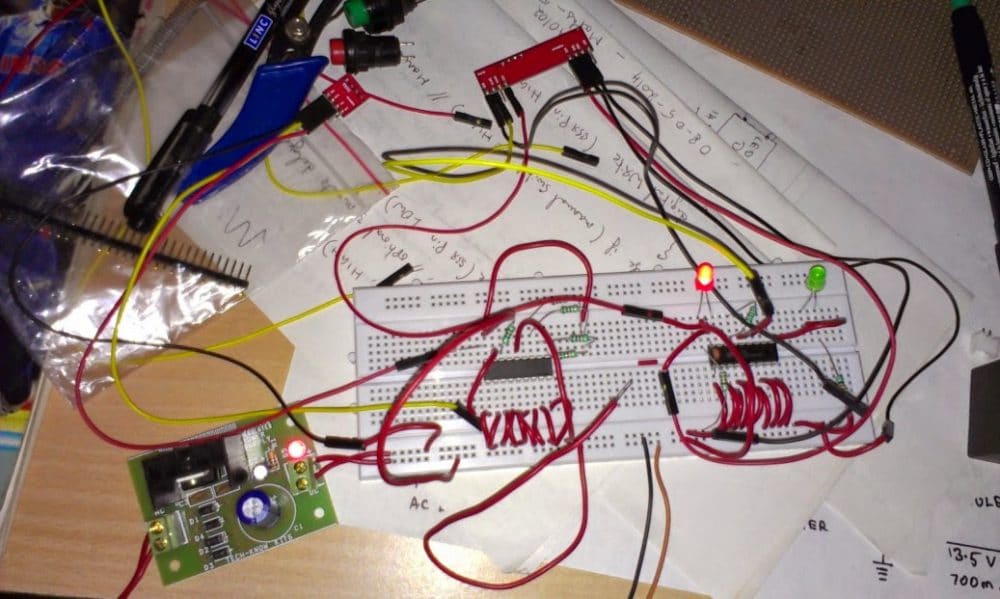
The above simple RF remote control circuit was successfully tested by Mr. Sriram on a breadboard, the following images of the built prototype were sent by him for reference.
Circuit Prototype Images
Making a 433 MHz, 315 MHz RF Remote Control with Relay Flip Flop
Building a hi-end remote control device using very few components today looks pretty plausible. The proposed remote control light switch circuit idea provides you with the opportunity of building and owning this amazing device through simple instructions.
Moreover the unit provides a 4-bit data to be exchanged between the transmitter and the receiver modules.
This Hi-tech remote control light switch enables you to control four individual lights or any electrical appliance for that matter from any corner of your house remotely using a single tiny remote control hand set.
Imagine switching a light, a fan, washing machine, computer or similar gadgets from any corner of your room without taking a step!
Doesn't that sound great?
Controlling a particular gadget remotely through a single flick of your finger definitely feels very amusing and amazing too.
It also gives you the comfort of doing an act without moving or getting up from a particular position.
The present circuit idea of a remote control light switch enables you controlling not only just a single light but four different electrical gadgets individually using a single remote control hand set.
Let’s try to understand its circuit functioning in details of the 433MHz Rx and Tx modules.
Transmitter (Tx) Circuit Operation
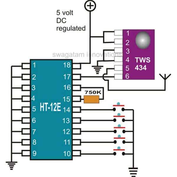
I have already discussed the wireless control modules in the above paragraphs, let’s summarize the entire description yet again and also learn how simply the stages may be configured into the proposed unit.
The first figure shows a standard transmitter module using the RF generator chip TWS-434 and the associated encoder chip the HOLTEK’s HT-12E.
The IC TWS-434 basically does the function of manufacturing and transmitting the carrier waves into the atmosphere.
However every carrier signal needs modulation for its proper execution, i.e. it needs to be embedded with a data that becomes the information for the receiving end.
This function is done through its complementing part – the HT-12E 4-bit encoder chip. It has got four inputs, which can be triggered discretely by giving them a ground pulse individually.
Each of these inputs produces coding which are distinctly different to each other and become their unique signature definitions.
The encoded pulse from the relevant input is transferred to the IC TWS-434 which carries forward the data and modulates it with the generated carrier waves and finally transmits it into the atmosphere.
The above operations take care of the transmitter unit.
Receiver (Rx) Circuit Operation
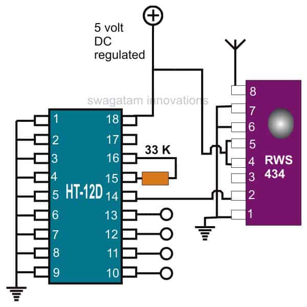
The receiver module does the above operations just in the opposite manner.
Here, the IC RWS-434 forms the receiving part of the module; its antenna anticipates the available encoded pulses from the atmosphere and captures them immediately as they are sensed.
The captured signals are relayed forward to the next stage – the signal decoder stage.
Just like the transmitter module, here too a complementing device the HOLTEK’s HT-12D is employed to revert the received encoded signals.
This decoding chip also consists of a 4-bit decoding circuitry and their outputs.
The received data is appropriately analyzed and decoded.
The decoded information gets terminated out through the relevant pin-out of the IC.
This output is in the form of a logic high pulse whose duration depends on the duration of the ground pulse applied to the encoder chip of the transmitter module.
How to use a Flip-Flop Relay Circuit at the Receiver module Output
The above output is fed to a Flip-Flop circuit using the IC 4017, whose output is finally used to switch the output load via a relay driver circuitry.
One such flip/flop idea is shown you may construct four of them to access each of the generated 4-bit data discretely and control four gadgets individually.
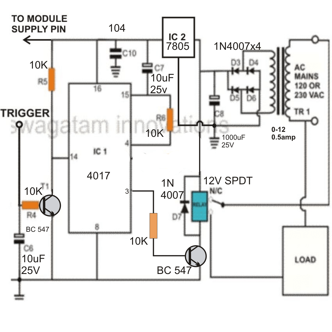
Whether you use it as a remote control light switch or to control many more appliances……the option is all yours.


Questions & Answers
It's greate, but where can i buy it or what is the name of the module because i cant fint it. Mabye its because i'm living in the netherlands
you can easily buy it online, search it on Google, and you will be able to find many online sources who market such devices.
But do you have a name of the modules?
433kHz RF Rx/Tx IC modules.
sorry it should be 433MHz not kHz
TELL me ,the RF modules name or model no. TRANSMITTER and RECEIVER circuit …
ones sw1 press that relay1 on,another press off like that only NA.
you can use the same circuits and configure them to work with different frequencies by setting up and matching the pins across A0 to A7 of the respective Rx/Tx pairs.
Can i connect relay directly to A to D outputs..
and,, its tested circuit..
No, you will have to use transistors drivers at those outputs for driving relays.
Thank u . ..and one more question i buy 434mhz rf module its also work with
this circuit..
The above circuits are also RF modules, sorry i did not understand your question
i have RF434 module , its working with your circuit..
sir , what is the cost of that RF Transmitter…………….or can i use a ir ……………or laser
around Rs.200/-
sir can i use your's rf Transmitter (https://www.homemade-circuits.com/2013/05/long-range-transmitter-circuit-2-to-5.html)in place of that rf module
that will work with FM radio only
hi sir,
i made this ckt.
but the ckt is not running ???
what can i do?
Hi ashwinkumar,
pls give more details about the problem.
hi sir,
can you teach me how to control(increase/decrease) the voltage by using remote control?
hi gekkoi, it will be quite a complex circuit, if possible i'll try to update it.
what i need to do this circute sir
i ts available all electric shop?
yes it's available readymade in the market, ask your local dealer about it
that you would using such a RF receiver could make a tester for car remote control?
Suppose that the DATA line is closely linked to the transistor, which would include the LED when the receiver receives a signal from the remote control?
for what application?
1.In this circuit, u shown up for 4 input and 4 output. Is it possible for 5 input and 5 output?? If yes means how to modify the circuit??
2. I am planning to implement this circuit for my home over tank. Bocz am in 1st floor and tank is in 5th floor. In the above circuit, Instead of the push switches in the transmitter section, if i arrange the terminals D0-D3 inside the tank means, as the water raising, the one by one D0-D3 wil get in contact through the water and this wil transmit the signal to the receiver. So the output LEDs in the receiver wil turn on according to water level.
3. In transmitter, suppose D0 is the tank empty state means there will be no contact to none of the terminals inside the tank, so the LED in the D0 of receiver wil turn off, at this state the motor should turn on.
4. After the water level started raising, the D3 of the transmitter will get contact , so the D3 LED of receiver wil turn on . At this state the motor should turn off.
Please provide me the circuit for this…
Thankyou..
The above circuit cannot be modified for 5 outputs, you can Google for a 5 output Tx/Rx circuit, you may get it.
Or you can buy the modules readymade from the market.
The input switches can be attached to relays and toggled through water sensor circuits.
We will discuss the circuit later, first you arrange the transmitter modules, we'll proceed further once it's done.
I did a long search in the net, but not able to find the 5 output Tx/Rx circuit. So i decided to continue the project with the above circuit itself. So i bought the RF module, encoder and decoder. Is is possible to connect the below link circuit with the above circuit??
https://www.homemade-circuits.com/2011/12/how-to-make-simple-water-level.html
yes it's possible, but it has only one relay, use it appropriately
sorry. Am not able to get a clear idea for connecting the two circuits. Can u able to provide me a circuit diagram for connecting the two circuits?? If water level goes below D0 means motor should power on, D1=half tank ( LED indiactor), D2= 3/4 tank (LED indicator), D3= full tank( LED indicator) and motor should shut off when water reached the D3 terminal. Please help…
It will be a little lengthy circuit, I will try to present it in my blog soon, in the meantime you can make both the circuits and keep them ready for the final integration as per my diagram.
Thank you, wil let u know when I make the both circuits…
Hai,
I made the above RF circuit and the below link water controller circuit. Now waiting for the integration section…
https://www.homemade-circuits.com/2012/02/how-to-make-ideal-automatic-water-level.html
Hi, Is everything working correctly? Please let me know the results of the units, meaning how the relays are working and how the water level controller is responding, if possible with pictures.
It will help me to design the new circuit correctly.
There is prob in the water circuit… I connected a CFL bulb in the relay… when i power on the circuit, the bulb is always in ON state because sensor B and C are not in touch. Even though I short circuited the sensor A and C, the light is still in ON state only. Pls help…
please send the close-up picture of the circuit that you have made, I'll try to find the fault by seeing the connections, if possible.
Hai, Ignore the previous command. The water circuit working good… The problem was due to loose connection. And now its working grt…
OK!! that's great Sriram,
Hai, Now one prob in RF circuit… when I power ON the RF circuit, The four output LEDs are in ON state only. And when i press the s1 switch means the output D LED is goes off, if I release the switch s1 means the output D LED is in ON state. Like that four LEDs are working. Its reverse order. I need if i press the switch means the corresponding LED should wrong. Is there any wrong will be in my circuit?? Pls help..
Hi, reverse the LED polarity and connect the resistor ends to positive…..
…please send pics if possible, so that I can post them in the above article……do it only if it's convenient for u….no force.
Thanks Mr.swagatam… I changed the polarity as u said… now it is working correctly…
Below are the pics:-
imgur.com/BMlRW7v
imgur.com/oLqSS4n
Now waiting for the integration of the circuits…
Thanks Sriram, I'll use the images for the above article.
I'll try to post the relay integrations soon and let you know….keep in touch meanwhile.
sure… thank you 🙂
Hai swagatam, how r u???
How is the integration process?? Am eagerly waiting for that…
Hi Sriram, I thought you might have already seen it, here's the link:
https://www.homemade-circuits.com/2014/05/remote-controlled-wireless-water-level.html
One doubt… suppose I am making two circuits with Tx1, Rx1 and Tx2, Rx2. Suppose if I press the switch in Tx1 means will it affect the Rx2??
yes it will unless you pair up the address pins uniquely for each Tx/Rx sets, please read the last section of the article above for a detailed info.
hiii swagatam, is there any way to increase its range or any other module available having range more than 500mtr? plz rply soon