• Skip to main content
  • Skip to primary sidebar

Homemade Circuit Projects

Need circuit help? Post them in the comments! I've answered over 50,000!

Blog | Categories | About | Contact | Calculators-online
You are here: Home / Meters and Testers / Make this Amplifier Power Meter Circuit

Make this Amplifier Power Meter Circuit

Last Updated on May 5, 2022 by Swagatam 6 Comments

Music Amplifiers have always intrigued us due to their massive amplifying capabilities which completely changes the dimensions of the delivered music outputs. Fundamentally it's the power of the amplifier that's always on the scanner and we find folks getting too obsessed by the power rating of their procured amplifier unit.

Table of Contents
  • Introduction
  • How the Circuit Functions

Introduction

However many of us completely fail to understand the technicalities of the above parameters and blindly agree to the manufactures spec sheet while buying an amplifier unit.In this article I have explained a very straight forward  circuit which can be easily built at home and used for determining the power of an amplifier output.

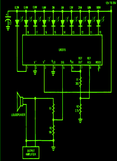
Here the proposed amplifier power meter circuit utilizes the magnificent IC LM3915 from TEXAS INSTRUMENTS, which takes the center stage and solely functions to convert the input from an amplifier to a direct LED readout, indicating the instantaneous power output levels.

How the Circuit Functions

The input to the IC is derived via a potential divider network R1/R2 built across the loudspeaker, connected to the amplifier.
The proposed design provides a maximum readout of 100 watts, however the circuit may be quickly modified for enabling higher readouts by adjusting the value  of R2.

The LEDs begin sequencing in response to the varying power output from the speaker.

Through some careful inspection of the readouts, the average intermediate LED display may be identified and the respective marking of the LED may be noted as the RMS value of the amplifier, however that might be relevant to the particular set volume level.

amplifier power meter circuit 1

You'll also like:

  • 1.  Simple MOSFET Tester and Sorter Circuit
  • 2.  Match Transistor Pairs Quickly using this Circuit
  • 3.  AC Ammeter Circuit for Measuring Current across 220 V Appliances
  • 4.  Digital Voltmeter Circuit Using IC L7107
  • 5.  Simple 1.5 V Inductance Meter Circuit
  • 6.  Simple Transformer Winding Tester Circuit

About Swagatam

I am an electronics engineer with over 15 years of hands-on experience. I am passionate about inventing, designing electronic circuits and PCBs, and helping hobbyists bring their projects to life. That is why I founded homemade-circuits.com, a website where I share innovative circuit ideas and tutorials. Have a circuit related question? Leave a comment.... I guarantee a reply!

Previous Post: « Single Transistor Radio Receiver Circuit
Next Post: 7 Simple Continuity Tester Circuits Explained »

Reader Interactions

Comments

  1. Felix.E says

    October 30, 2022 at 8:06 am

    Engineer… as always, many thanks…
    1. Up to how much power could it measure with the modification… Only R2.?
    2. What would be the modification to measure the maximum power.
    3. Could use as a visual meter on an amplifier.

    Reply
    • Swagatam says

      October 30, 2022 at 11:28 am

      Thank you Felix,
      Yes you can measure any range of power simply by modifying the R2 value….or by replacing R2 with a preset or potentiometer.

      Reply
  2. Jesubiyi says

    March 10, 2018 at 4:02 am

    I don’t want to temper wit ur rated calibratn. I need it as u stated. 0.2w to 100w

    Reply
    • Swagatam says

      March 10, 2018 at 10:14 am

      you will need to calibrate it using a 100K pot

      Reply
  3. Jesubiyi says

    March 9, 2018 at 1:31 pm

    Waoo I love this… I hv 2nos this ic since 4years ago I use 1for battery check 2nd one not in use.
    I ll build it but u forgot to add the value of R1.since u hv calibrated the cct. what’sd value of R1? thanks in advance

    Reply
    • Swagatam says

      March 9, 2018 at 3:10 pm

      Thanks jesubiyi, you can use 100K pot with a 10K resistor for R1, this can be adjusted for getting the correct calibration across LED bar graph

      Reply

Need Help? Please Leave a Comment! We value your input—Kindly keep it relevant to the above topic! Cancel reply

Your email address will not be published. Required fields are marked *

Primary Sidebar

Subscribe to New Circuit Ideas

Categories

  • Arduino Projects (87)
  • Audio and Amplifier Projects (132)
  • Automation Projects (17)
  • Automobile Electronics (101)
  • Battery Charger Circuits (83)
  • Datasheets and Components (104)
  • Electronics Theory (143)
  • Free Energy (37)
  • Games and Sports Projects (11)
  • Grid and 3-Phase (19)
  • Health related Projects (25)
  • Home Electrical Circuits (12)
  • Indicator Circuits (14)
  • Inverter Circuits (87)
  • Lamps and Lights (142)
  • Meters and Testers (69)
  • Mini Projects (46)
  • Motor Controller (64)
  • Oscillator Circuits (27)
  • Pets and Pests (15)
  • Power Supply Circuits (108)
  • Remote Control Circuits (50)
  • Security and Alarm (64)
  • Sensors and Detectors (101)
  • Solar Controller Circuits (59)
  • Temperature Controllers (42)
  • Timer and Delay Relay (49)
  • Transmitter Circuits (29)
  • Voltage Control and Protection (37)
  • Water Controller (36)

Calculators

  • Battery Back up Time Calculator
  • Capacitance Reactance Calculator
  • IC 555 Astable Calculator
  • IC 555 Monostable Calculator
  • Inductance Calculator
  • LC Resonance Calculator
  • LM317, LM338, LM396 Calculator
  • Ohm’s Law Calculator
  • Phase Angle Phase Shift Calculator
  • Power Factor (PF) Calculator
  • Reactance Calculator
  • Transistor Astable Calculator
  • Transistor base Resistor Calculator
  • Voltage Divider Calculator
  • Wire Current Calculator
  • Zener Diode Calculator
  • Filter Capacitor Calculator
  • Buck Converter Calculator
  • Boost Converter Calculator
  • Solar Panel, Inverter, Battery Calculator
  • Wire Current Calculator
  • SMPS Transformer Calculator
  • IC SG3525, SG3524 Calculator
  • Inverter LC Filter Calculator

People Also Search

555 Circuits | 741 Circuits | LM324 Circuits | LM338 Circuits | 4017 Circuits | Ultrasonic Projects | SMPS Projects | Christmas Projects | MOSFETs | Radio Circuits | Laser Circuits | PIR Projects |

Recent Comments

  • Swagatam on 2 Compact 12V 2 Amp SMPS Circuit for LED Driver
  • Alan Bishop on AC Motor Speed Controller Circuits using Back EMF
  • Swagatam on Real MPPT Solar Charger Circuit Using Arduino, LCD, and Manual/Auto Switch
  • Swagatam on AC Motor Speed Controller Circuits using Back EMF
  • Swagatam on DC to DC Converter Circuits using SG3524 [Buck, Boost Designs]

Company

  • Privacy Policy
  • Cookie Policy
  • About Me
  • Contact
  • Disclaimer
  • Copyright
  • Videos
  • Sitemap

Social Profiles

  • Twitter
  • YouTube
  • Instagram
  • Pinterest
  • My Facebook-Page
  • Quora
  • Stack Exchange
  • Linkedin
  • © 2025 · Swagatam Innovations