In this post I have explained a relatively easy lipo battery balance charger circuit which is designed to continuously scan and charge the connected cells of the battery.
The idea was requested by Mr. Schindler and Mr. Emil Jan Thomas Baticulon.
Charging 6 Li-Po Packs
The concepts are very well written, concise and clear. Thank you so much for the deep coverage of the charging subject.
Have you encountered the need to charge several identical lipo packs regularly? I have that very need, it is time consuming to recharge 6 high power packs containing 4 cells each every few days.
I propose a single cell charger that scans all cells via the balance plugs and serves up the requirement per need during a partitioned interval of the scan period.
Arduino sketch, shift registers, discrete coupling and a plan to stitch it together... there is where I bid you to guide me to a viable implementation. If you'd be so kind?
Charging 18650 Li-Ion Pack
Good day,
I just recently found your blog and upon further reading your post it's very helpful with or without electronic background and i appreciate your work.
I have a project in mind but I am stuck with it, My idea was how can I charge 13pcs 18650 li-on battery in series connection with balancing charger?. Can you help me with it and add this to your work?
Thank you,
The Design and Working
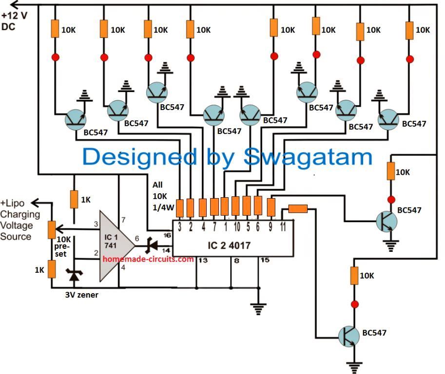
As shown in the following diagram, the proposed Lipo battery balance charger circuit can be implemented rather effortlessly using a couple of IC stages.
Let's try to understand how the circuit is intended to function:
- You can see two DC supply sources in the circuit. One is a fixed 12V for the ICs and the relay driver stages, second is the 4.2V for charging the Lipo cells through the relay contacts. (Make sure to connect the grounds or the negatives of both the supplies together in common)
- This 4.2V is also fed to the non-inverting pin#3 of the op amp via the preset.
- Referring to the circuit diagram below, when power is switched ON, a HIGH signal from one of the IC 4017 outputs randomly switches ON one of the relays through the connected BC547 driver.
- The relay contacts connects the 4.2 V to the relevant Lipo cell. If the cell is discharged it causes the 4.2 V to instantly drop to its discharged level, which may be anywhere from 3 V to 3.9 V.
- This drop causes the op amp pin#3 potential to drop below its pin#2 potential.
- Due to this, the output of the op amp goes low, which does not have any effect on pin#14 of the IC 4017.
- This situation allows the connected Lipo cell to start charging, and as a soon as it reaches the 4.2 V mark, as per the setting of the preset, pin#3 potential goes higher than pin#2 potential.
- This instantly turns the output of the op amp high, toggling pin#14 of the IC 4017 with a clock pulse.
- The above action causes the existing output pin HIGH from the IC 4017 to shift to its next pinout.
- This HIGH causes the next relevant BC547 relay stage to switch ON and connect the next Lipo cell in the same way as explained above.
- The cycle keeps repeating for all the 10 cells, until all the cells charged sequentially.
Control Circuit Diagram
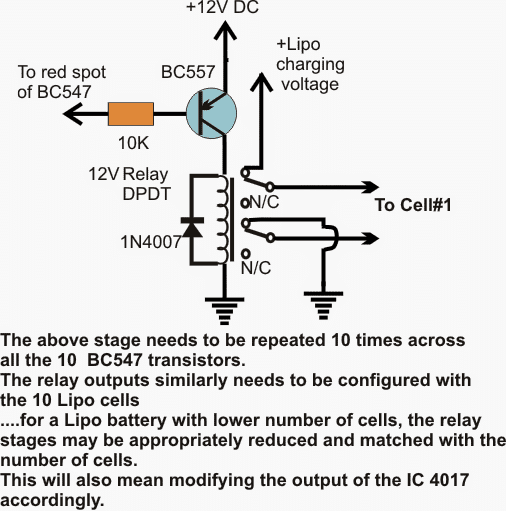
The second diagram below is the relay driver stage which needs to be repeated 10 times and the base of the BC557 associated with the red spots of the relevant BC547 stages from the first circuit below.
Relay Driver Schematic
If the cells are 3.7V rated, the opamp preset is adjusted such that its output pin#6 just goes high when the charge level across the cell reaches around 4.2V.
How to Set up the Balance Charger Circuit
For setting this up, a sample 4.2V may be fed at the shown preset's upper lead, and the preset slider adjusted to make pin#6 of the opamp just high (positive).
- With all the positions connected as depicted in the diagrams and power switched ON, let's assume that at the onset pin#3 of the IC4017 is high which in turns activates the associated BC547, BC557 and the connected relay contacts.
- Cell#1 now begins charging, which drags down the supply voltage across the preset pin#3 of the opamp to may be say 3.4V or whatever may be the initial discharge level of the cell#1.
- While this happens, pin#3 of the opamp experiences a lower potential than it's pin#2 ensuring a low signal at its pin#6 and the pin#14 of the IC 4017.
- As cell#1 of the lipo battery charges, the terminal voltage of this cell slowly increases until it reaches the stipulated 4.2V mark.
- As soon as this happens, pin#3 of the opamp also is subjected at this voltage forcing its output pin#6 to go high, which in turn prompts the IC4017 to shift its pin#3 logic high to it next pin#2, toggling the driver stage of this pin into action.
- The above shift activates the charging of the second cell of the lipo battery in the same manner as it did for the first cell.
- The process now continues and repeats itself by scanning and charging the cells in steps continuously.
- Thus the lipo battery cells are maintained with optimal charging level through the above explained lipo battery balance charger circuit as long as the circuit remains connected with the lipo cells.
Question from Avid Reader Mr. Prithviraj
I am an avid follower of your website www.homemade-circuits.com. Your circuits are always working and awesome for a hobbyist like me to learn and try. I need a small guidance on a question I have regarding LiPo Battery pack.
I am trying to make an e-Bike on my own. I'm building a 24V 6S 18Amp Lithium Ion battery pack which will contain a BMS board for balance charging. My question is, if I try to charge this battery pack directly with a 24V 10A SMPS will that be safe?
I mean, since I already have a BMS built into the battery pack, can I directly connect the SMPS output to the battery pack input/output lines? I am using a 20A 6S BMS in the battery pack. So, also please advise if the 10Amp charger taking is safe too. I will be really grateful if you could please advise.
My Reply:
Yes, you can use the 24V SMPS for charging the mentioned battery. The battery will be safely charged since a BMS is already present in the system.
Comments
please what value of resistor ( ohms and watts) can I use to discharge a 40ah la battery sets and 100ah set, to prevent overcharging. thanks
To prevent overcharging of your battery you must use an automatic over charge cut-off circuit, or limit the voltage to 0.5V below the actual full charge level of the battery.
Dear Sir, thank you for your website & this circuit that I stumbled across, I like this circuit & plan on constructing it & testing it out soon, just one quick question though if i may, I notice on the schematic that the diode between the output pin of the op amp & the clock pin of the 4017 is a zenner diode symbol, but I’m guessing that it is meant to be an ordinary silicon diode, such as 1N914 or 1N4148 etc etc etc, unless I am blind? I see no reference to this diode anywhere, so can you please confirm my assumption, or if I’m wrong please specify the type & if it really is a zenner diode, then can you give me the relevant voltage please.
Many thanks & best regards Paul.
Thank you Paul, for your interest in this circuit.
The zener diode makes sure that the output HIGH from the opamp reaches the pin#14 of the 4017 IC only when the opamp output is legitimately “HIGH”. The zener diodes blocks any unwanted leakage voltages that may be present at the opamp output and prevents false triggering of the 4017 IC.
The zener voltage can be 30% of the Lipo cell voltage.
Alternatively, you can try adding a preset between pin#1 and pin#5 of the 741 IC to nullify its output offset voltage and then eliminate the zener diode entirely:
https://www.homemade-circuits.com/wp-content/uploads/2023/09/offset-nulling-procedure-for-IC-741.jpg
Please can I use this circuit to charge 48P 3S lithium ion battery pack?
You can use it…
How many amps needed to charge 48P 3S 18650 Battery pack at 4.2V
Thank you for your wonderful work.
Can you please tell me what is the mAh rating of each cell?
2400mah
Thank you sir.
OK so the optimal charging current required will be
2400 x 48 = 115200 / 2 = 57600 = 57.6 amps
So I need 4.2V 57.6A Battery charger to charge 48P 3S Lithium Ion battery pack using the charging circuit above?
Thanks for the good work.
That’s correct!
Thank you sir.
Keep the good work.
Dear Swagatham,
Thank you very much for leading me to this project. However I doubt if this would be a practical solution.
The main reason being , This circuit feed the charging voltage to individual battery one battery at a time with a 12v charger (for a 12 v lead acid battery ) or whatever be the individual battery voltage.
This is not the practical situation.
For a ups working on 48v , 4 batteries are connected in series, UPS connected to the battery using two wires , charging and discharging done using the same cables. So the charging voltage is not 12 v , but 48v (actually 60v).
In case of Solar panel and using MPPT for charge controlling, the output of MPPT is connected to the battery in parallel to UPS. This ensures that if there is excess current available and if there is more load , the excess current is fed directly tot he ups to run that load.
In this scenario , It would be very difficult or even unfruitful to reduce the charging voltage (which would increase charging current too). Correct me if I am wrong.
Rather, a circuit that directs the higher charge of cell to another of lower , just like a tilting pipe line, might be a better and simpler idea, equalizing them. I hope you understood my idea. I think this is what the commercial product does. Consider this when you get time.
Thks.
Dear Suresh, the above circuit is a battery balance charger which are specifically required for batteries that are connected in series. It is impossible to maintain equal charging of a series connected battery unless each battery is charged separately within the series system. If you apply 60 V to a series of 4 batteries in series with only two wires then that will never be able to maintain equal charge levels across all the 4 batteries unless if the batteries itself are built with exact specifications and characteristics.
Or may be I am missing something.
Hi Swagatam, please is it possible to use mosfets or transistors in place of the relays. In other words the mosfets or transistors will be in charge of switching the battery terminals.
Hi Sam, presently I do not have this design with me, but will surely try to figure it out and will post it soon if I happen to get it.
Hello sir Swagatam, my name is Carlos I from Buenos Aires Argentina. Could you build 18650 battery balancer circuit with lm358 to charge 4 18650 in series … Thank you very much
Hi Carlos, presently I do not have a 3.3V balancer circuit, if it is possible I will try to design it and post it for you!
Good day Sir, please help me to solve the controversy on battery equaliser for strings of lead acid battery- 8-10 number. Some say it is essential, while others say not essential, Provided they are same age and type. Thanks
Hello Seun, yes it is essential if the batteries are in series…However if you keep the total full charging limit slightly less than the recommended full charge level then you can avoid the equalizer.
Thanks for the enlightenment. What’s the recommended full charge level even while a pulsed desulfator is used to avoid using equaliser.
You are welcome! For a 12V lead acid battery you can use 14.1V for each battery, as the full charge level.
Hello Swagatam,
Would you possibly have this schematic in a kicad project? or another pcb designing software?
Greetings from an electronics student.
Hello Pointy, sorry I do not have the PCB designs, but any professional PCB maker will quickly do it for you.
I am already subscribed. I was looking at this circuit and it just hit me that this is just what the doctor ordered for me, however looking at the schematic one of the zener diodes are labeled as 3v. Am I to presume that both should be 3v? If so then this will work perfectly. Thanks in advance.
I am glad you found the post helpful. Yes both the zeners can be 3 V, however I would recommend the pin#6 zener to be replaced with a RED LED, and connect a 4k7 resistor between pin14 of the IC 4017 and ground.
Hi,
Thanks for the wonderful project of this Lipo Battery Balance Charger, one question is seems it charge the battery cells one by one? is this same as other charger or just a special case here.
is it possible to charge few cells simultaneously?
Did you make one ? how’s that?
Best
Adam
Hi, I don’t about the other chargers, but this is how the individual cells are supposed to be scanned and charged in a balance charger circuit, according to my knowledge.
Interesting. Judging by the circuitry, the battery series can be balance charged while lively connected to other sources (with very carefully separation of course). Is this correct assumption?
Has anyone made any commercial offerings for this yet?
Yes you are correct, usually the load is connected across extreme ends of the series battery…
I have been following your dear svagatam site for a long time. I have great circuit ideas according to my needs Thank you for bringing this to the world.
Thank you very much, I appreciate your feedback!
Please is there any component that can be used to transfer charge from one battery to another apart from super capacitors, can ordinary electrolytic cap do likewise. Thanks sir.
No, ordinary capacitors might not work, or you might need huge numbers of them
Thanks sir, Swag. Is there any other way to transfer charge apart from super capacitors?
Hi Seun, there’s no other way to transport electric power except with batteries and super capacitors
Hi Swag,
I like to automatically Balance between LiFePO4 cells that are in series.
LiFePO4 cells in series will go out of balance.
Not fast and huge difference, still..the do not automatically balance between the cells.
In this situation series can be 4 to 16 cells or 500.. number of series is not relevant.
(Nominal 3.2v, max 3.65v)
This is for solar energy storage, off-grid.
24/7 in use, always charging or discharge (day/night)
My total capacity is 1016Ah@51.2v (S16)
It is not needed information for the question, but give insight in the usage.
The idea is simple, 2 cells A and B have voltage difference.
For example:
Cell A = 3.36v
Cell B= 3.34v (0.02v out of balance)
“flying cell” (capacitor) would charge from Cell A and discharge at Cell B.
(Capacitor acts like small battery and is paralleled with cell A then B and back to A again)
In a situation of 16 cells in series one would need 15 X this setup.
Placed between each 2 cells.
If it would have symbol ∆ then it would look like:
A ∆ B ∆ C ∆ D
Or cell 1∆2∆3∆4 for 4 cells in series.
It doesn’t have to work fast.(with solar setup one thinks in days or weeks to get Balance, it doesn’t need to be in a few hours)
It does need to use the cell as own power source for the (small) PCB .
Cell A connect to the capacitor, then disconnect from the capacitor and the capacitor connects to cell B.
In a loop, with 5 seconds (?) connect to each cell.
(I do not know how long it takes for a capacitor to charge)
I do not know if there needs to be a disconnect time between both cells (1second?) To prevent interference / bad vibes for the cells or stable DC output.
I do understand that bigger capacitors are more expensive and probably need more time to charge and discharge.
Based on the capacity of the cells and possible imbalance one needs to decide on the size of the capacitor.
It would be great to get an example value for 100Ah LiFePO4 cell
Flip flop or automatic changeover switch on pre-set timing.
Obviously with low own power usage, and preferably low cost ????
Thank you!!
Hi Fhorst, I am having difficulty in understanding the use of the capacitors for the balancing act. Are you trying to implement a “capacitor dump charging” process, where the respective capacitors will be charged by the solar panel, and then the capacitors will be discharged on the cells for charging them?
Please provide more details regarding the purpose of the capacitors, and the circuit operation for implementing the balancing of the cells.
Please Swag, I want to ask if Battery management system (Equaliser) can equalise 48v battery system using 48v solar system and 24v solar system for
48v charging the 48v battery system.
Please see what equalization means, whch will answer your question quickly:
https://batteryuniversity.com/learn/article/equalizing_charge
Thanks sir for the link, please can I use a 48v battery system comprising of different sizes of battery with a BMS, will the BMS balancing be effective in improving battery life.
Adeyemi, if the BMS is correctly rated as per the battery then it will help to ensure longer life for the battery.
Hi,
thank you for your advice:). I think that I just figured it out, the op-amp, compares the 4.2 to the batteries voltage and tells the 4017 to stop charging when the comparing has shown that the battery is at 4.2 volts?
Is my understanding sort of correct, or I am completely wrong? And also about the present, how do I measure that the output is high, is it like binary to measure with an oscilloscope? Have a good one :).
When the opamp detects 4.2V, it sends a pulse to the IC 4017 so that its output moves to the next lipo cell and connects its status with the op amp input so that the opamp now starts scanning this new cell’s charging status, until it get fully charged at 4.2 V and the cycle continues.
To measure the instantaneous voltage of a connected cell, you can attach a voltmeter or an oscilloscope across the input supply source for the lipo
Hi,
I’m planning to adapt your circuit to charge my batteries.I just wondered though, what happens when all the batteries in the pack have charged up to 4.2V ? What stops the relays from continuing to cycle on and off, testing the battery status at a rapid rate, that would result in chatter and reduction of the relay lifespans? Some sort of delay is desireable to prevent this from happening or an auxiliary circuit testing the total battery pack voltage and waiting until this has dropped. Such a circuit probably should avoid heavily draining the battery under charge. What are your thoughts? Thank you.
Hi, it cannot scan at a rapid rate because the op amp output will not clock the pin14 of 4017 until the relevant cell charges fully. The output of the opamp wil become high only once the cell charge reaches 4.2V which can take a lot of time.
What happens when all the cells are fully charged? Wouldn’t the circuit keep cycling rapidly?
yes, it should keep cycling, and scanning the levels.
Hello, this circuit is for people who have a good knowledge of electronics, if you cannot understand then you should not attempt it.
It is 4.2V at which the the charger must cut off…so 4.2V is the max threshold.