Linear Hall-effect ICs are magnetic sensor devices designed to respond to magnetic fields to produce a proportionate amount of electrical output.
It thus becomes useful for measuring the strength of magnetic fields, and in applications that require an output switched through magnetic triggers.
The modern hall effect ICs are designed with immunity to most mechanical stressful conditions such as vibrations, jerks, shocks and also against moisture and other atmospheric pollutions.
These devices are also immune to ambient temperature variations which otherwise could make these components vulnerable to heat producing incorrect output results.
Typically, modern linear Hall Effect ICs can work optimally over a temperature range of -40 to +150 degree Celsius.
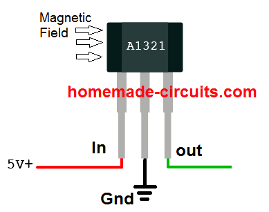
Basic Pinout Diagram
Ratiometric Specified Functioning
Many standard linear Hall-effect ICs such as A3515/16 series from Allegro or DRV5055 from ti.com are “ratiometric” by nature, wherein the devices quiescent output voltage and sensitivity vary in accordance with the supply voltage and ambient temperature.
The quiescent voltage could be typically half the supply voltage. As an example if we consider the supply voltage to the device to be 5V, in the absence of a magnetic field its quiescent output would normally be 2.5V and would vary at a rate of 5mV per Gauss.
In case the supply voltage was to increase to 5.5V, the quiescent voltage would also correspond to 2.75V, with the sensitivity reaching the 5.5mV/gauss.

What is Dynamic Offset
Linear Hall-effect ICs such as the A3515/16 BiCMOS incorporate a proprietary dynamic offset cancellation system with the help of an in-built high frequency pulse so tat the residual offset voltage of the Hall material is controlled appropriately.
The residual offset could arise normally due to over-molding of the device, temperature discrepancies or due to other relevant stressful situations.
The above feature renders these linear devices with a significantly stable quiescent output voltage, well immune to all types of external negative impacts on the device.
Using a Linear Hall-effect IC
The Hall-effect IC may be connected with the help of the given connections, where the supply pins must go to the respective DC voltage terminals (regulated).The output terminals may be connected to an appropriately calibrated voltmeter having a sensitivity matching the Hall output range.
Connecting a 0.1uF bypass capacitor directly across the ICs supply pins is recommended in order to safeguard the device from externally induced electrical noise or stray frequencies.
After powering up, the device may require a few minutes of stabilization period during which it must not be operated with a magnetic field.
Once the device gets internally temperature-stabilized, it may be brought under the influence of a external magnetic field.
The voltmeter should immediately register a deflection corresponding to the strength of the magnetic field.
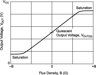
Identifying Flux Density
For identifying the flux density of the magnetic field, the devices output voltage may be plotted and located over the Y-axis of a calibration curve, the intersection of the output level with the calibration curve would confirm the corresponding flux density on the X-axis curve.
Linear Hall Effect Application Areas
- Linear Hall-effect Devices could have diverse application areas, a few of them are presented below:
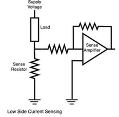
- Non-Contact Current sensing meters for sensing current externally passing through a conductor.
- Power sensing meter, identical to the above (watt-hour metering) Current trip-point detection, where an external circuitry is integrated with a current sensing stage for monitoring and tripping a specified over current limit.
- Strain gauge meters, where the strain factor is magnetically coupled with the Hall sensor for providing the intended outputs.
- Biased (magnetically) sensing applications Ferrous metal detectors, where the Hall effect device is configured to detect the ferrous material through relative magnetic induction strength detection Proximity sensing, same as the above application, the proximity is sensed by approximating the relative magnetic strength over the Hall device.
- Joy-stick with intermediate position sensing Liquid-level sensing, another relevant sensing application of the Hall device. Other similar application which involve magnetic field strength as the main medium along with the Hall effect device are: Temperature/pressure/vacuum sensing(with bellows assembly) Throttle or air valve position sensing Non-contact potentiometers.
Circuit Diagram using Hall Effect Sensor
The hall effect sensor explained above can be quickly configured through a few external parts for converting magnetic field into electrical toggling pulses for controlling a load. The simple circuit diagram can be seen below:
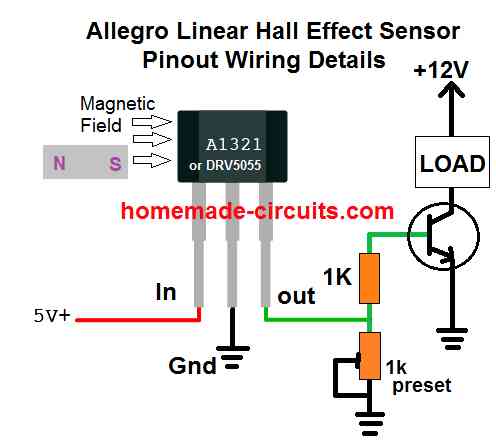
In this configuration, the hall effect sensor will convert a magnetic field within a specified proximity and will convert it into a linear analogue signal across its "out" pin.
This analogue signal can be easily used for driving a load or for feeding any desired switching circuit.
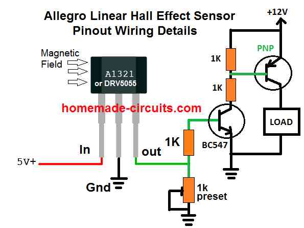
How to Increase Sensitivity
The sensitivity of the above basic hall effect circuit could be increased by adding an additional PNP transistor, with the existing NPN, as shown below:
Using Opamp
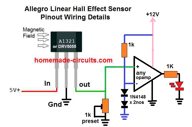
The DRV5055 hall effect sensor can be also integrated with an operational amplifier for getting the switch ON results in response to a magnetic proximity with the hall effect device.
Here the inverting input of the op amp is set to fixed reference of 1.2 V using two series 1N4148 diodes, while the non-inverting input of the op amp is configured with the output of the hall effect for the intended detection.
The 1k preset is used for setting up the switching threshold at which the op amp is supposed to switch, depending on the strength and the proximity level of the magnetic filed around the hall effect.
In the absence of a magnetic field, the hall effect sensor output remains below the set threshold of the op amp inputs.
As soon as the output from the hall effect goes above the non-inverting threshold of the op amp, as set by the preset and the reference level of the inverting input, the output of the op amp turn high, causing the LED to switch ON. The LED could be replaced by another circuit stage for a switching ON some other desired load.


Comments
Hello,
I am not an electronics type guy at all.
I am attempting to build a current limiting device for use on 120VAC. The plan is to be able to shut down the AC power at either 5 amps or 10 amps until the load has been reduced below the 5 or 10 amp limit.
I know I would need to have two separate circuits that would be selected depending on which current limit value is required. I have been looking at the Allegro ACS723 (xLLCTR-5AB and xLLCTR-10AB) devices and they look promising. I’m just not sure about implementing these devices to control a relay in order to open the AC power wires. I ran across your circuit on this project and was wondering if I might substitute the output of the ACS723 device in place of the A1321 device output? Or would that be too easy? My existing circuit has +28VDC and I can add a +5VDC and/or a +12VDC if required.
hello, A hall effect sensor is no way related to a current limiting application, and therefore it cannot be used.
Instead you can see the concept explained in the following article:
https://www.homemade-circuits.com/mains-over-load-protector-circuit-for/
Hello again,
I might not have explained myself correctly or fully.
https://www.digikey.com/en/datasheets/allegromicrosystemsllc/allegro-microsystems-llcacs723datasheetashx
The ACS723 is a current sensor that uses a built in Hall sensor to track the amount of current flow from the supply to the load. As the load current increases the voltage output of the device increases. My plan is to use this device to monitor the load and if the desired current setting is exceeded the output would be used to toggle a logic circuit (TBD) and subsequently to open a relay and shut off the power to the load.
I have thrown together a very rough sketch of my idea if I can send it to you somehow.
Regards,
Ron
Hello, I went through the details in the datasheet, and have come up with the following simple design as per your desired specifications:
The load could be wired through the relay contacts and and in series with the input AC coupled with the IC.
In order to latch the relay you can additionally connect the pin2 of the IC with the the collector of the transistor via a 1N4148 diode.
Hi,
This looks really good. Three more questions please.
#1: I have a switched ground that is presently controlling the relay such that a ground keys the relay and supplies the 120VAC to the load. Can this be connected to the circuit so that the relay is energized and provides the 120VAC to the load unless the load hits the maximum current? At the maximum current limiting point the relay de-energizes and stays open until the load is either removed or the current falls below the maximum limit at which point the relay will energize again?
#2: Is the LED used to provide a visual indication of the relay status?
#3: My relay coil is driven by +28VDC. If I am reading the specifications correctly for the BC547 I should be able to use 28VDC instead of +12VDC with no other changes?
Thank you so much,
Ron
Hi, this circuit also uses a ground to switch the relay via BC547, so everything looks fine.
However, when the relay switches, the current will be removed which will prompt the relay to switch again, and this may cause rapid chattering of the relay at the thresholds. To avoid this, a latching feedback will be necessary. Also make sure to add a 47uF/25V capacitor across base/emitter of the transistor to ensure a delay effect on the relay switching.
28V can be used with BC547, but the relay coil current must be within 60 mA
Hello Swagatam,
Thanks for this article, it is very interesting and possibly will point me in the direction I am looking to go. My electronics is very basic and I am on a huge learning curve.
I am trying to build a discrete magnetic field detection application.
I made a prototype using a reed switch (nc) and a pnp transistor. It worked but the reliability of the reed switch is not consistent.
I like the idea of a Halls effect sensor as this is more robust and reliable.
My question is, using the diagram (allegro linear hall effect sensor pintout wiring details above) can it be made more sensitive? ie detect a magnetic field 4-6 inches? I am not sure if this would involve changing the A1321 Hall effect sensor and upgrading the resistor from 1k to something higher? Would the supply voltage, being a 9v battery be too great for the Hall effect sensor?
the load (box) after the transistor (pnp?) can that drive a buzzer or some other ‘alarm’ device. I really need to keep the device as simple and as robust as possible. The magnetic field is generated by a 18v DC electromagnet.
I sincerely thank you for your opinion and help on this.
Hello Shandor, I have the updated the required design at the end of the above post, this should increase the sensitivity to a great extent.
The supply to the hall must be 5 V, so you may need to regulate the 9V to 5V through an IC 7805 or simply using a 1K, 4.7 V zener network.
The load can e replaced with a alarm or a relay.
hi, Swagatam,
i am working on a anemometer using linear hall effect sensor, but i need to transmit the output signal to 20 feet from my roof top to my house, can you suggest any idea on how to do so ,as the voltage is getting droped.
Hi Raj, I think you can convert the output to 220V AC through a transformer, and then convert it back to the required DC at the end of the 20 feet wire. 220V AC will have lower loss through the 20 feet wire compared to DC
Hi Swagatam,
I don’t have a pull up resistor on the Vout pin of the LM293P and thanks for the explanation. Given the output of 2.5V, that’s perfect for me as I don’t have to mess around will voltage level changers given the max input pin voltage on the Pi is 3.3V.
Hi Richard,
Without a pull up resistor the output should be zero volts permanently, 2.5 V is not normal. It means your opamp could be malfunctioning. With a pull up resistor it will be either 0V or 5V. This 5V then can be converted to 3.3V
Hi Swagatam,
Making my hall circuit, I’ve seen a few things that may be of interest to others.
1. Using the analogue hall sensor, when I placed it directly next to the cat flap magnet to make the back bias and the iron slug on the bottom of the flap door is next to it, I get 0v shown on the comparator Vout. If the flap is barely opened, I get fluctuating values from 0.5v and up. If the flap is moved completely open, I get 0v again.
Now measuring when the flap is open and closed is more tricky if you get 0v when it is both fully open AND closed, so I put the sensor about a quarter inch from the magnet so still 0v when flap closed but the voltage now only starts to go up when the flap is open about and inch and stays up even when fully open and returns to 0v when closed. So good.
2. I’m a bit confused by the voltage level, taking it from 5v down to 3.3v so the Pi input GPIO pin won’t fry. From what I read about comparators, they will check the input of two separate sample voltages and will output the Vcc voltage powering the comparator itself on the Vout. I’ve got 5V powering the comparator, Vin+ is 2.50v and Vin- is 0.5mv, yet when the flap is open I see 2.50v max on Vout and not 5v. 2.50v is fine for the Pi as it’s over 1.65v which the pin will see as a digital HIGH which I can code as “flap open”. Does the LM293P only output the largest voltage seen?
Hi Richard,
Did you connect the output of the compartaor with a pull-up resistor? The LM393 or 293 have their output connected to an open transistor collector internally.
You will have to connect a 1K or any resistor upto 10K from this output to the +5V line. Then the output will be either +5V or 0V depending on the input conditions, anything between this could indicate a fault in the comparator.
For more info you can refer to the LM311 example in this article:
https://www.homemade-circuits.com/comparators-using-ic-741-ic-311-ic-339/
Hi Swagatam,
I hope you can help because I can’t seem to find the answers / experts elsewhere and your explanation of hall sensors here is great.
The problem.
I have a Raspberry Pi (I can’t use an Arduino for other reasons) and I want to be able to detect when a cat flap door opens. There is a slug of iron crimped onto the bottom of the flap door and that is attracted to a neodymium magnet inside the flap, underneath the slug.
In a nutshell, I want to put a hall sensor between the magnet and the iron slug and when the slug disturbs the magnetic field, I get a voltage or flag change that I can use in code to say “the flap has been used”.
Effectively a back biased magnet setup. The magnet is mounted horizontally with N facing outside the house and S facing in.
I bought an A17301 analogue sensor and APS11700/60 digital magnetic switches. All three connected and detected when a magnet was brought close to them but did not show any change when then I moved the iron slug near them. I’m guessing the digital switches are preset and I need a $2000 sensor programmer to set it to what I need.
So then I saw this guy make a ferrous detector with a hall sensor (he doesn’t say which sensor he’s using but has to be analogue). That would be fine, replace coin with iron slug and bingo but I’m sure the A17301 already has an opamp in it.
http://www.youtube.com/watch?v=JSQ_q0_9emY
So I’m stuck.
Do I then…
A. Buy a basic linear omni polar analogue hall sensor, make this ferrous circuit and work out the output with a simple ADC to connect to the Pi.
B. Is there an all in one hall sensor that I can use with the existing magnet which will give me a 0 or 1.
C. Is there another hall sensor option?
I can’t imagine it’s this hard, it’s not detecting a camshaft rotating, it’s a cat flap. 🙂
TIA
Richard
Hi Richard, the application you are trying to implement looks too basic to have any problems. At first I thought may be I was missing something, but after reading your explanation a few times I still couldn’t find anything complex in it.
However my first question is why do you wish to use an iron slug for the detection? Why not fix the magnet itself on the cat flap door and use it for triggering the hall sensor.
Secondly, did you check the output from your Hall sensor separately with a meter and with the iron slug disturbance?
Remember, only an external op amp would be able to detect a difference of even a 0.2V when the iron slug is brought near the sensor. I would recommend a LM393 op amp, for building the op amp circuit.
So if you are seeing a difference at the output even by a 0.2V or 0.5V that would be enough to force the external op amp to toggle its output.
Hope this solves your problem!
Hi,
Thanks for getting back to me so quickly.
The reason for not attaching a magnet directly to the flap door is two fold.
1. I wanted to keep the flap as stock as possible and not attach anything to the flap door otherwise I would have gone for a reed switch solution.
2. The magnet and the iron slug have been matched by the flap manufacturer and it’s unlikely I would find the same crimped mounting for a magnet on the door which wouldn’t change the dynamic of the swing, plus the cat knows how much weight to push against it now and doesn’t like change. Nuts, yes.
For testing I put a 5V VCC feed in and measured the VOUT. The sensor has self calibration and gave a solid 0 when a magnet was brought close.
It was more of a sanity check if the saturation of the back bias magnet would be zeroed out with the sensors internal calibration and be close enough that the difference with moving the iron slug would throw some voltage back from the VOUT. Clearly I misunderstood that. 🙂
I’ve got some LM393s so I’ll make up the circuit with the existing A17301 and see what the result is.
Thanks again.
Richard
That sounds great! will wait to see how it goes!
So… all good.
I made the circuit up as per the ferrous detector link but I swapped out the op amp for a LM293P comparator. I tested it with a 5V Arduino using the builtin LED for high and low.
Held the A 7301 hall sensor next to the cat flap magnet with flap door closed, LED went off. Opened the flap, LED came on.
Will solder it up on a perma-proto board already in the project adding some 5V to 3.3V level shifting before adding connecting it to the Pi.
BTW the project is The Integrated Cat Flap, a ML flap with all the components inside the flap. If the flap detects prey in the cat’s mouth, it will issue an audio warning and servo lock the flap. Now with the hall sensor I can detect if the flap is moved before the camera sees the cat, the cat is going out and if the camera sees the cat first, then the flap is moved, the cat is coming in.
http://www.raspberrypi.org/forums/viewtopic.php?t=172114
Thanks for the help.
Richard
Awesome! Glad you could do it so quickly! I love cats too! Have many of them playing in my backyard!