In this post I have explained what EEPROM is, how data is stored on built in EEPROM on Arduino board’s Microcontroller and also practically test how to write and read data on EEPROM by a couple of examples.
Why EEPROM?
Before we ask what EEPROM is? It is very important to know why EEPROM is used for storage in first place. So that, we get clear idea on EEPROMs .
There are lot of storage devices available these days, ranging from magnetic storage devices like computer hard disks, old school cassette tape recorders, optical storage medium like CDs, DVDs, Blu-ray disks and solid state memory like SSD (Solid State Drive) for computers and Memory cards etc.
These are mass storage device which can store data such as music, videos, documents etc. from as low as few Kilobytes to multi-Terabytes. These are non-volatile memory which means, the data can be retained even after the power is cut-off to the storage medium.
The device which delivers ear soothing music or eye popping videos; such as computer or smartphone; stores some critical data such as configuration data, boot data, passwords, bio-metric data, login data etc.
These mentioned data cannot be stored in mass storage devices for security reasons and also these data could be modified by users unintentionally which could lead to malfunction of the device.
These data takes only few bytes to few Megabytes, connecting a conventional storage device like magnetic or optical medium to processor chips are not economically and physically feasible.
So, these critical data are stored in the processing chips itself.
The Arduino is no different from computer or smartphones. There are several circumstances where we need to store some critical data which must not get erased even after the power is cut-off, for example sensor data.
By now, you would have got an idea why do we need EEPROM on microprocessors and microcontrollers chips.
What is EEPROM?
EEPROM stands for Electrically Erasable Programmable Read Only Memory. It is also a non-volatile memory which can be read and write byte wise.
Reading and writing byte-level makes it different from other semiconductor memories. For example flash memory: reading, writing and erasing data in block-wise manner.
A block can be few hundreds to thousands of bits, which is feasible for mass storage, but not for “Read Only Memory” operations in microprocessors and microcontrollers, which need to access byte by byte data.
On Arduino Uno board (ATmega328P) it has on board 1KB or 1024 bytes of EEPROM. Each byte can be accessed individually; each byte has address ranging from 0 to 1023 (that’s total of 1024).
Address (0-1023) is a memory location where our data will be stored.
On each address you can store 8-bit data, numeric digits from 0 to 255. Our data is stored in binary form, so if we write number 255 into EEPROM it will store the digit as 11111111 in an address and if we store zero, it will store as 00000000.
You can also store text, special characters, alphanumeric characters etc. by writing appropriate program.
The construction details and working are not discussed here which might make this article lengthy and we may make you sleepy. Head towards YouTube or Google, there are interesting article/videos regarding constructional and working of EEPORM.
Do not confuse EEPROM with EPROM:
In a nutshell EPROM is an Electrically Programmable Read Only Memory meaning it can be programmed (store memory) electrically, but can’t be erased electrically.
It utilizes bright shine of Ultraviolet light above storage chip which erases the stored data. EEPROM came as replacement for EPROM and now hardly used in any electronic devices.
Do not confuse Flash Memory for EEPROM:
A flash memory is a semiconductor and non-volatile memory which is also electrically erasable and electrically programmable, in fact flash memory is derived from EEPROM. But the block-wise memory access or in other words, the way of memory is accessed and its construction makes different from EEPROM.
Arduino Uno (ATmega328P Microcontroller) also sport 32KB of flash memory for program storage.
Lifespan of EEPROM:
Like any other electronic storage medium, EEPROM also has finite read, write, erase cycles. But the problem is; it has one of the least lifespan compare to any other kind of semiconductor memory.
On Arduino’s EEPROM, Atmel claimed about 100000 (one lakh) write cycle per cell. If your room temperature is lower the greater the lifespan of EEPROM.
Please note that reading data from EEPROM does not affect the lifespan significantly.
There are external EEPROM ICs which can be interfaced Arduino with ease with memory capacity ranging from 8 KB, 128KB, 256 KB etc. with life span of about 1 million write cycles per cell.
That’s concludes the EEPROM, now you would have gained enough theoretical knowledge about EEPROMs.
In the following section I have explained how to test the EEPROM on arduino practically.
How to Test EEPROM in Arduino
To implement this, all you need is a USB cable and Arduino Uno board, you are ready to go.
From the above explanations we understood that EEPROMs have Address where we store our data. We can store 0 to 1023 locations in Arduino Uno. Each location can accommodate 8-bits or one byte.
In this example we are going to store data in an address. To reduce complexity of the program and to keep the program short as possible, we are going to store single digit integer (0 to 9) on an address from 0 to 9.
Program Code#1
//------------------Program Developed by R.GIRISH (Fixed)-------------------//
#include <EEPROM.h>

int inputAddress = 0;
int inputValue = 0;
int ReadData = 0;

void setup() {
  Serial.begin(9600);
  while (!Serial) { delay(10); } // wait for serial on some boards

  Serial.println("Enter the address (0 to 9):");
  inputAddress = readSingleDigit();     // returns 0..9
  Serial.print("You have selected Address: ");
  Serial.println(inputAddress);
  Serial.println();

  delay(500);

  Serial.println("Enter the value to be stored (0 to 9):");
  inputValue = readSingleDigit();       // returns 0..9
  Serial.print("The value you entered is: ");
  Serial.println(inputValue);
  Serial.println();

  delay(500);

  Serial.print("It will be stored in Address: ");
  Serial.println(inputAddress);
  Serial.println();

  delay(500);
  Serial.println("Writing on EEPROM...");
  EEPROM.update(inputAddress, (uint8_t)inputValue); // update avoids unnecessary writes
  delay(500);
  Serial.println("Value stored successfully!!!");
  Serial.println();

  delay(500);
  Serial.println("Reading from EEPROM...");
  delay(400);
  ReadData = EEPROM.read(inputAddress);
  Serial.println();
  Serial.print("The value read from Address ");
  Serial.print(inputAddress);
  Serial.print(" is: ");
  Serial.println(ReadData);
  Serial.println();
  delay(200);
  Serial.println("Done!!!");
}

void loop() {
  // nothing here
}

// --- helper: read single numeric digit from Serial and return 0..9
int readSingleDigit() {
  while (true) {
    if (Serial.available() > 0) {
      int ch = Serial.read();
      // consume any extra newline/cr/carriage
      if (ch == '\r' || ch == '\n') continue;
      // accept ASCII digits
      if (ch >= '0' && ch <= '9') {
        // flush remaining line (optional)
        flushSerialLine();
        return ch - '0';
      } else {
        // invalid char: show message and keep waiting
        Serial.println();
        Serial.println("Invalid input. Please type a single digit 0 to 9 and press Enter.");
      }
    }
  }
}

// consume until newline to clean the buffer
void flushSerialLine() {
  while (Serial.available() > 0) {
    int c = Serial.peek();
    if (c == '\n' || c == '\r') { Serial.read(); break; }
    Serial.read();
  }
}
OUTPUT:
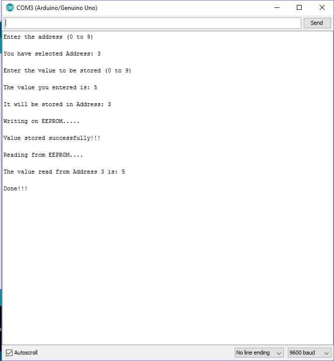
Once the code is uploaded, open the serial monitor.
It will ask you enter address ranging from 0 to 9. From the above output, I have entered address 3. So, I will be storing an integer value in the location (address) 3.
Now, it will prompt you to enter a single digit integer value ranging from 0 to 9. From the above output, I have entered value 5.
So, now the value 5 will be stored in the address location 3.
Once you enter the value, it will write the value on EEPROM.
It will show a success message, which means the value is stored.
After a couple of seconds it will read the value which is stored on the commented address and it will show the value on the serial monitor.
In conclusion, we have wrote and read the values from EEPROM of Arduino’s microcontroller.
Now, we are going to use the EEPROM for storing password.
We will be entering a 6 digit number (no less or no more) password, it will be stored in 6 different address (each address for each digit) and one additional address for storing “1” or “0”.
Once you enter the password, the additional address will store the value “1” indicating that password is set and the program will ask you to enter the password to turn ON the LED.
If the additional address stored value is “0” or any other value is present, it will ask you to create new 6 digit password.
By the above method, the program can identify whether you have already set a password or need to create a new password.
If the entered password is correct the build in LED at pin # 13 glows, if the entered password is incorrect, LED won’t glow and serial monitor will prompt that your password is wrong.
Program Code#2
//------------------Program Developed by R.GIRISH (Fixed)-------------------//
#include <EEPROM.h>

const int passExistAdd = 200;
const int LED = 13;
const int WORD_ADDR_BASE = 0; // addresses 0..5 used for 6 digits

int word[6];
int checkWord[6];

void setup() {
  Serial.begin(9600);
  pinMode(LED, OUTPUT);
  digitalWrite(LED, LOW);
  while (!Serial) { delay(10); } // wait for Serial on some boards

  int passwordExist = EEPROM.read(passExistAdd);

  if (passwordExist != 1) {
    Serial.println();
    Serial.println("No password present. Enter a new 6-digit numeric password (type digits sequentially):");
    for (int i = 0; i < 6; i++) {
      word[i] = readSingleDigitWithPrompt(i + 1);
    }

    // Save to EEPROM (use update)
    for (int i = 0; i < 6; i++) {
      EEPROM.update(WORD_ADDR_BASE + i, (uint8_t)word[i]);
    }
    EEPROM.update(passExistAdd, 1);

    Serial.println();
    Serial.print("Password saved successfully: ");
    for (int i = 0; i < 6; i++) Serial.print(word[i]);
    Serial.println();
    Serial.println("Please reset the device to continue.");
    // do not freeze CPU in a tight loop; blink LED to indicate wait-for-reset
    while (true) {
      digitalWrite(LED, millis() % 1000 < 500 ? HIGH : LOW);
      delay(200);
    }
  } else {
    Serial.println();
    Serial.println("Please enter the 6-digit numeric password:");
    // read stored password into checkWord
    for (int i = 0; i < 6; i++) {
      checkWord[i] = EEPROM.read(WORD_ADDR_BASE + i);
    }

    const int MAX_ATTEMPTS = 3;
    int attempt = 0;
    bool ok = false;

    while (attempt < MAX_ATTEMPTS && !ok) {
      // read user input
      for (int i = 0; i < 6; i++) {
        word[i] = readSingleDigitWithPrompt(i + 1);
      }

      // compare
      ok = true;
      for (int i = 0; i < 6; i++) {
        if (word[i] != checkWord[i]) {
          ok = false;
          break;
        }
      }

      if (!ok) {
        attempt++;
        Serial.println();
        Serial.println("Wrong Password!!!");
        if (attempt < MAX_ATTEMPTS) {
          Serial.print("Attempts left: ");
          Serial.println(MAX_ATTEMPTS - attempt);
          blinkLedTimes(2, 150);
          Serial.println("Try again:");
        } else {
          Serial.println("Maximum attempts reached. Locking for 30 seconds.");
          // blink LED for lock duration
          unsigned long lockStart = millis();
          while (millis() - lockStart < 30000UL) {
            digitalWrite(LED, (millis() / 250) % 2 ? HIGH : LOW);
            delay(100);
          }
          Serial.println();
          Serial.println("Lock period ended. Please power-cycle or reset to try again.");
          // stop here
          while (true) {
            digitalWrite(LED, LOW);
            delay(500);
          }
        }
      } else {
        break;
      }
    }

    if (ok) {
      digitalWrite(LED, HIGH);
      Serial.println();
      Serial.println("Password correct.");
      Serial.println("LED is ON");
      Serial.println();
      Serial.println("Press Reset Button if you want to restart.");
    }
  }
}

void loop() {
  // nothing here
}

// --- helper: read single numeric digit from Serial and return 0..9, with a small prompt
int readSingleDigitWithPrompt(int position) {
  Serial.print("Digit ");
  Serial.print(position);
  Serial.print(": ");
  int d = readSingleDigit(); // function below
  Serial.println(d);
  return d;
}

int readSingleDigit() {
  while (true) {
    if (Serial.available() > 0) {
      int ch = Serial.read();
      if (ch == '\r' || ch == '\n') continue;
      if (ch >= '0' && ch <= '9') {
        flushSerialLine();
        return ch - '0';
      } else {
        Serial.println();
        Serial.println("Invalid input. Please type a digit 0..9 and press Enter.");
        // flush any non-digit until newline
        flushSerialLine();
      }
    }
  }
}

void flushSerialLine() {
  while (Serial.available() > 0) {
    int c = Serial.peek();
    if (c == '\n' || c == '\r') { Serial.read(); break; }
    Serial.read();
  }
}

void blinkLedTimes(int times, int msDelay) {
  for (int i = 0; i < times; i++) {
    digitalWrite(LED, HIGH);
    delay(msDelay);
    digitalWrite(LED, LOW);
    delay(msDelay);
  }
}
OUTPUT:
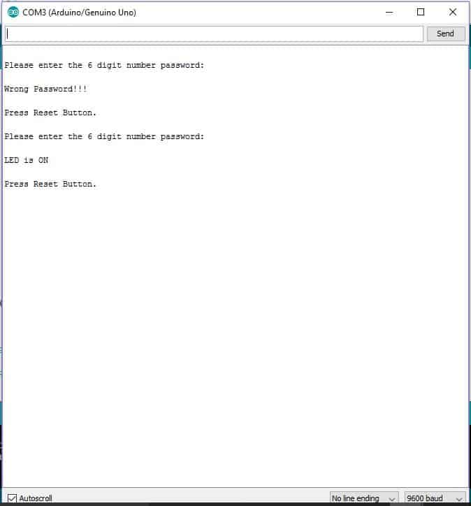
Open the serial monitor; it will prompt you to create a 6 digit number password.
Enter any 6 digit password and note it down and press enter. Now the password has been stored.
You may either press the reset button or disconnect the USB cable from PC, which make the supply to Arduino board interrupted.
Now, reconnect the USB cable, open serial monitor, which will prompt you to enter the saved 6 digit password.
Enter the correct password the LED will glow.
If you want to change the password change the digit from the code:
int passExistAdd = 200;
The above line is the additional address which I have explained before. Change anywhere from 6 to 1023. 0 to 5 addresses is reserved for storing 6 digit password.
Changing this additional address will fool the program that password is not created yet and prompt you to create a new 6 digit password.
If you have any questions regarding this EEPROM in Arduino tutorial, please express in the comments, you may receive a quick reply.


Comments
Hello sir, h r u.. very interesting topic. .. I have doubt-
U might have seen many led display in roads and shops- different patterns of led, scrolling word and sentence etc. How to do this?whether they are using eeprom?
U have any circuit for this?
Hi Sinu, the complex ones which show many many patterns surely are based on microcontrollers, presently I do not have the required codes for this type of project
I dont want code sir . I only want the circuit or theory. means how they are doing. If you have any idea..
Sinu, I’ll try to get it, if I happen to find it will update it for you…
Thankyou sir…hope to listen from you soon
hi Swagatam
Nice article and easy to understand. according to my understanding is that if you want to build a project that will be used permanently like in home electronics etc. then you have to write your programs in the EEPROM. AM I RIGHT? SINCE THE DATA STORED WILL NOT BE ERASED EVEN AFTER POWER FAILURE.
THANKS A LOT
Hi Abba, thanks for liking the article.
I have not yet gone through the article and I am yet to learn microprocessors.
It was written by Mr. GR, who a microcontroller expert, and he would be knowing the exact answer to your question, You can contact him anytime through his FB ID.
Sir
Can you please help me
I need a circuit
When I power the circuit it will be relay on .
And when sensor or anything detect green color it will be turn the relay off . If get any other color never turn off the relay .
Sir please help me by providing this circuit
Hi,
Triggering a circuit with colour is possible with RGB colour sensor with a Arduino or any microcontroller.
Regards
Hi GR,
you can send the article to me for publication. you can write about the module and project article separately.
OK!
Farhan, triggering a circuit with color detection looks difficult, I am not sure how to do it…
I really understand your explanation. I did it at School HND level.
Thank you!
Hallo ,
das eeprom wurde sehr gut und verständlich erklärt.
viele grüße
walter
Vielen Dank! Froh, dass es Ihnen gefallen hat …