Here I have tried to investigate a few enhanced triac based phase controller circuits which can be recommended for controlling or operating inductive loads like transformers and AC motors much safely than earlier traditional triac based circuit dimmer circuits.
Using Triacs for Controlling AC Loads
A Triac is a semiconductor device used for switching AC loads. Normally it is recommended that the loads that needs to be operated through triacs should be resistive in nature, meaning loads which incorporate coils or capacitors heavily, must be avoided.
Therefore in general loads which convert energy into heat like incandescent bulbs or heaters etc only become suitable with triacs as the switch and devices like transformers, AC motors and electronic circuits are a big NO!
However recent developments and researches have improved things to great extents and today new triacs and the involved improved circuit configurations have made it absolutely safe even for the triacs to be used for switching purely inductive loads.
I won't be discussing the technical areas of the configurations, keeping the new electronic hobbyists in mind and for the sake of simplicity.
Let's analyze a few of the researched designs which boast to support triacs with inductive loads.
Triac Control Circuit Only Suitable with Resistive Loads
The first circuit shows the general way of using a triac and a diac combination for implementing the required controlling of a particular load, however this design is just not suitable with inductive loads.
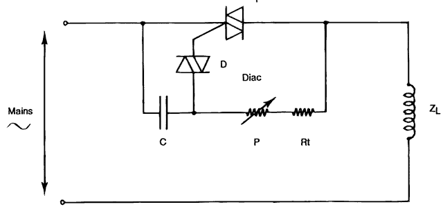
The circuit incorporates the principle of triggering with synchronization across the triac. The configuration is the simplest in its form and has the following advantages:
The design is very simple and cheap.
Use of only two end terminal wire and absence of any external power supply.
But one big disadvantage of this design is its incapability of working with highly inductive loads.
Triac Control Circuit Reasonably Suitable for Operating Inductive Loads
However a little contemplation shows that the above circuit can be simply modified into the design shown in the next diagram.
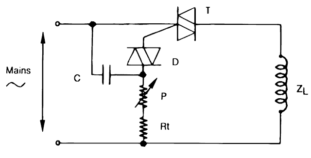
The principle here now gets transformed to triggering of the triac with synchronization by the mains voltage.
The idea to very extent neutralizes the above issue and becomes very much coordinated even with inductive type of loads.
Please note that in the above design very interestingly, the position of the load and the resistor connection has been changed for acquiring the intended results.
The advantages can be assessed as follows:
Again a simple design and also is very low cost.
Better control of even loads which are inductive by nature.
As usual no external power source is required for the functioning.
The disadvantages though are the involvement of 3 terminal wire ends for the intended connections.
The operations become very asymmetrical and therefore the circuit cannot be used for controlling highly inductive loads like transformers.
Triac Control Circuit Ideally Suitable for Highly Inductive Loads like Transformers and AC Motors
An intelligent tweaking of the above circuit makes it very much desirable even with the most tabooed inductive loads like transformers and AC motors.
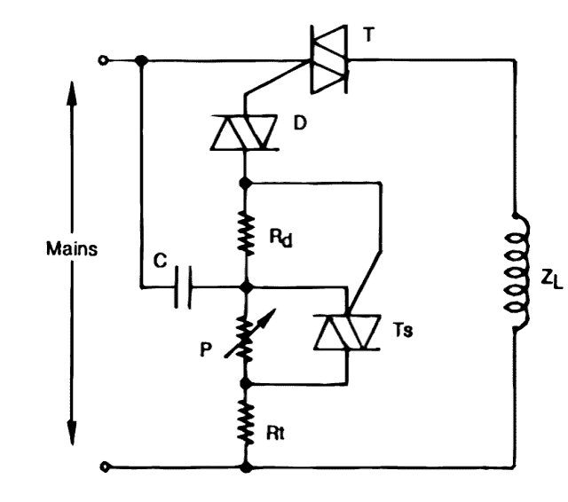
Here another small sensitive triac is cleverly introduced for rectifying the major issue that's primarily responsible for making triacs so unsuitable with inductive loads.
The second small triac makes sure that the triac is never switched OFF and blocked completely, by generating a pulse train, keeping the triac alive and "kicking" all the time.
The advantages of the above final design may be marked with the following points:
Very simple design,
Superb accuracy while controlling highly inductive loads,
No use of external power supply.
The above circuit was exclusively developed by the SGS-THOMSON Microelectronics applications laboratory and used with success for a wide range of equipment.
COURTESY:


Comments (60)
Thanks for the all of the posts, I found the answer I was looking for. The basic starting components for this circuit: Triac Control Circuit Ideally Suitable for Highly Inductive Loads like Transformers and AC Motors.
Thanks for the feedback… glad the problem is solved!
What list of values would be good to use in this circuit: “Triac Control Circuit Ideally Suitable for Highly Inductive Loads like Transformers and AC Motors”
Hi Swagtam. Thanks for all the great work you do.would you please asign values to the circuit designed to control inductive loads. Here is my case.120 to 37 VAC. I need lo control voltaje to transforme primary windings. Anpat 24v 25A DC 600W battery charger.
Thank you Louis, you can simply do it by wiring the 120V AC primary side of your transformer in series with a fan dimmer, which are explained in the following article:
https://www.homemade-circuits.com/simple-ceiling-fan-regulator-circuit/
Hello Swagatam,
Thank you for the great article. I am working on a circuit using a Triac to shut off the output should the voltage rise above the normal voltage. The circuit works great with the light bulb. I am using an optocoupler to turn on or off by powering the gate, however, when I tested it with the inductive cooker, the circuit acted very weirdly probably due to being highly inductive. I was wondering if your diagram in the article would work. Sorry, I am new to triac.
Hello Thomas,
Since you are using the triac as an ON/OFF switch, it should not matter whether the load is resistive or inductive.
You can see some good examples in the following article which shows how to configure a triac with a load correctly:
https://www.homemade-circuits.com/simple-triac-triggering-circuits-explained
Is this circuit usefull for regulating power trafo for welder-TIG?10A 400v as max at the primary side?- off corse using a triac withc is capable of this size of power-? With kind regards-B. S. Nielsen
Yes triac dimmer circuits can be used to control any AC load. Since the welder trafo works with AC, its power can be controlled using a triac dimmer circuit.
ING.. YOU COULD SEE A CIRCUIT TO REGULATE THE WASHER BRUSH MOTOR IS VERY HIGH RPM 14000….I WANT 2800 TO 3000 RPM BUT STABLE AND WITHOUT LOSING TORQUE WITH n PWM 555 TOGETHER WITH THIS CIRCUIT… YOU COULD ATTACH ,, I I TRY THE 3RD DIAGRAM AND IT WORKS BUT WITH LOAD IT HAS A COST –
You can try the following circuit. It is without 555 but is very good:
Complete details is provided in the following article:
https://www.homemade-circuits.com/how-to-make-simplest-triac-flasher/
Hello engineer… I am very happy with your page, I have done several projects and they work perfectly with your help… now I need the values of the components of the TRIAC CONTROL CIRCUIT IDEALLY SUITABLE FOR HIGHLY INDUCTIVE LOADS LIKE TRANSFORMERS AND MOTORS AC..
IS FOR: A Brushed Washing Machine Motor..the MCA52/64-148 1.4 Amp
Thanks Felix,
Actually I am not 100% sure about the parts, but as a starting point you can try the following components:
C = 0.022uF/400V
Rd = 470 ohms 1/4 watt
P = 470K pot
Rt = 100K 1/4 watt
D = diac DB-3
T = Triac BTA41
Ts = Triac = any low power triac
i don’t have any question yet just want to say thank you for this website, it brought me to road on electronics, my God bless you sir
You are most welcome sunny!
Do you have a circuit for controlling the primary of a 8kv 10ma ozone transformer, I can do it with a ww2-5k pot , can’t get one in nz , normal dimmers don’t work need an inductive load type .txt me 021908513, urgent .
normal dimmers can work both with resistive and inductive loads, so you can use them as long as the working supply voltage is below the triac voltage spec
Hello,
I have to change primary voltage of the transformer using a triac. For example, I have to drive about 12VAC or 8VAC Lamp in secondary voltage of the transformer by adjusting the primary voltage in any time. ???? Can I use AC Welding Circuit which in SGS- Thomson Application Notes with 1 piece transformer to change primary voltage of the transformer ?
You can simply connect the primary of the transformer in series with any standard light dimmer unit, and it will do the job for you.
Hello Swagatam,
I want to change primary voltage of the transformer using a TRIAC. So, My load is not resistive. My load is inductive 🙂 Can I use AC Welding Circuit which in SGS- Thomson Application Notes ?
Hello Fatih, yes you can use it without any doubts
Thank you so much Swagatam.
To make a adjustable primary voltage of the transformer, I should change potentiometer value (P1 and P2) in AC Welding Circuit which in SGS- Thomson Application Notes. Is that enough ?
Thanks Fatih, yes you can use P1 and P2 for controlling the welding output
HI BRO,
I WANT TO DESIGN PROTECTION CIRCUIT FOR THREE PHASE INDUCTION MOTOR LIKE UNDER VOLTAGE, OVER VOLTAGE, OVER CURRENT ,ETC.I DONT KNOW HOW TO START THE PROCESS.IS THERE ANY IC’S AVAILABLE IN MARKET FOR THIS DESIGN KINDLY HELP ME FOR THIS DESIGN.
THANK YOU,
Hello Moni, I don’t have a protection circuit for a 3 phase supply at this moment, if it’s feasible I will try to design and post it soon in this website.
Hi – many years ago I had a 160 amp arc welder in which the transformer primary was controlled by an electronics circuit but the circuit and or components (scr) were not up to the job and soon packed up leaving the machine on max current. The inductive control circuit above would seem to be a good solution to restoring controllability. What components and values would be needed to control a 7kva transformers? Thanks in advance for your help.
Hi, I have not yet practically confirmed the above designs so I cannot suggest anything regarding these concepts.
However you can try the second last design circuit explained in the following article which is a tested design, and its quite similar to above with its working principle.
https://www.homemade-circuits.com/how-to-make-simplest-triac-flasher/
You can replace the triac with BT141A/800 and replace the DC1 diac with a neon bulb as this one:
https://www.homemade-circuits.com/neon/
Please, the last circuit for inductive load, does it mean it will reduce the power consumption of the load like freezer or what, why is necessary for inductive loads. I have tried your circuit on dimmer, it’s great in reducing the power consumption. Thanks so much for this
Dayo, yes it will reduce consumption, as well as the output power of the unit. But I am not sure about the resultant impact on appliances like freezers.
I am glad you could build the linked dimmer circuit successfully
please, can this circuit be used for a water pump machine, refrigerator and air conditioner?
sorry I am not sure about, you may have to test it practically
Hello sir Swagatam,
Thank you very much for sharing this article. I want to use the circuit to control my a.c ceiling fan, so I have some questions:
1. Can use it for that purpose without any problem? If yes,
2. I want to connect the circuit in such a way that I will use discrete resistor values (say, 4 resistors) instead of the 220k pot, such that I will use a rotary switch to switch between the resistors to give the fan different rotating speeds (four stages of equal intervals).
Is this possible? If yes,
3. What resistor values do you suggest that I use, and what should be thier power ratings?
4. I want to have a fifth state that will bring the fan to a total stop, i.e. four stages for different speed levels and the fifth stage to switch off the fan. How do I achieve this?
Anticipating your usual prompt response. Thank you.
Hi Godson, I won’t recommend the above experimental designs, instead you could try the last diagram having 5 step rotary switch controlled fan dimmer from the following article
https://www.homemade-circuits.com/how-to-make-simplest-triac-flasher/
I have checked the link. It is just perfect for my application. Thank you very much sir.
Keep up the good work!
Thank you for introducing some of the basic and advanced Triacs circuits. Typically, when adjusting the input of the tranphomer, it produces very loud noise. The circuit you introduced by SGS-THOMSON. I see That’s great, but I’m asking you to try it. If I want to try this circuit and put in
using arc welding machine control
Is it good? Please give me some time. Thank you very much.
you mean to say you want to control a welding transformer power with this circuit? That may be possible, just make sure to use a heavy duty triac (100 amp, 400V) and a compatible diac…if you are unable to get a suitable diac then you can try replacing it with high grade neon bulb
typo correction: I mistakenly wrote connects instead of concepts
hello, resistive loads you ca simply use the connects explained in the following article
https://www.homemade-circuits.com/2012/04/how-to-make-simplest-triac-flasher.html
Hey Swagatam, thanks for you website, clear descriptions and all the time and effort you share. But… I do have a question ;).
I built the last of the above circuits, and it works fine, but with Rd = 120 Ohm. The inductive load is just a 60 Watt ventilator (I plan to use the circuit for heavier inductive loads still). However, when using it with this 60 W load I can not get the rpms below 60% of full power. Can I simply increase Rd to lower the output power further? Thanks
Thanks Wtg, According to me increasing the value of the pot might help to increase the range on the lower side, because the speed basically depends on how fast or how slow the capacitor is allowed to charge and discharge, therefore by slowing down the charging rate of the capacitor we would be able to decrease the speed of the motor proportionately.
However you can experiment with the other components also, there are hardly anything in the circuit so identifying the right one will be just a matter of minutes 🙂
Hi, for dimming purpose you could try a standard triac dimmer circuit as shown in the last diagram from the following article
https://www.homemade-circuits.com/2012/04/how-to-make-simplest-triac-flasher.html
The triac should be a BTA41 600 for controlling massive currents even upto 40 amps
the dimmer circuit must be employed in series with the mains primary side of the transformer
Hi
I need to switch a transformer using a triac controlled by a controller. the transformer is rated 230/120 V 1.1 KVA. Ineed to switch only during the first few cycles. Can you help me out with this?
Satvik
you can use any triac based timer and use it for switching your transformer for the desired amount of time:
Hello, I love your page, I have a question what values do I need for Rt,Rd,Ts,P,T,D,C if I want to use a transformer of 1100 Watts aprox? (in mains I have 220 Volts and 50 Hz)
…..confirm the set up using a 200 watt bulb first, after that you can replace it with the trafo
You can try those values but i cannot guarantee the results.
a 10amp triac might work if adequately heatsinked.
nothing would burn actually since your transformer is in series with the circuit, and if at all anything burns it would be one of the components not your house wiring.
Make sure you have an experienced/qualified technician with you while you attempt this experiment.
hi again,if I use the values that you wrote up in the blog:
Rt can be = 10k
P= 220k pot,
Rd = 6k8,
C = 0.1uF/250V
Ts = BT131
and instead the BTA41 a TRIAC of 10 Amps max. should it work? I do not know very much of electronics and I dont´t have any idea on how calculate the values of the components I just dont want to burn anything.
Thanks !
hello, I am not sure about the exact component values that may be suitable for your application, however today the modern triacs mostly have in-built snubbers and protection against inductive loads, so I think you can comfortably use any standard fan dimmer circuit and use a high power triac such as a BTA41/800 with it for the mentioned load without any concerns.
Timer On time is 3min, and off time is variable 2 to 8 min.
you can use the following circuit, just replace the relay with a triac
https://www.homemade-circuits.com/2012/04/how-to-make-simple-programmable-timer.html
Hello sir,
I just need a circuit like timer. but the load is of 60 W 340V AC Inductive.
Please help me in building the circuit using BT169D or any best suitable scr or triac for inductive load
Hello Sarang,
inductive load becomes an issue only when it's switched with a frequency through a triac, just for ON/OFF timer operation it won't pose any problem. you can use the following circuit:
https://www.homemade-circuits.com/2013/07/simple-triac-timer-circuit.html
I HAVE REQUIRED 100 AMP AC SINGLE PHASE MOTER SPEED CONTROL CIRCUIT DIA GRAM ,
THANKS
AZIZ JAMAL;I
greetings sir pls if am wrong pls correct me. Rt i guess is a normal resistor of 10k? then how about Rd? that has a value of 6k8? i dont get that part pls
Hi Ekeh,
I think Rd = 6k8 is incorrect, it should be a low value resistor positioned just for protecting the diac from current surges…..a 100 ohm 1/4 watt resistor will probably do the job.
Yes BT169 is an SCR, …..it should be BT131 instead.
BT169 seems a SCR and not a triac, am I missing something?
can you provide the link or original application note for SGS THOMSON
Google the words given in the courtesy image at the bottom of the page, you will get it immediately.
only two pins need to be used, the center and any of the remaining ones.