A free energy collector circuit helps to convert surrounding radio frequency waves to electric power and can provide 40 watts to 10 watts indefinitely.
The Circuit Concept
An option to increase the output power is achievable through proper set-up of an antenna. Placing an antenna in a close proximity of a large metal object helps generate additional power.
The wire of an antenna should be more than 150 feet long, which has to be placed horizontally on a higher platform to derive the best result.
The more the higher an antenna is set, the more it is able to act efficiently. However it is advisable to keep the circuit closer to an antenna.
The proposed free energy collector circuit on the other hand, also acts as a passive detector. As the large metal object passes wave, there is an increase in power. One major usage of this process is in the field of volcanic studies.
Selecting the Antenna
The sensitivity of an antenna is capable to detect variation of energy from earth and is often used to receive warning signal for a possible seismic activity.
So it can be summed up that the placement of an antenna is very much crucial for a better output. Also one can use many of these circuits to construct and connect their inputs together, to produce ample energy to run electricity in a house. However to note, each unit needs their own antenna to construct the same.
The Radio Frequency power varies based upon a location. If the set-up location is close to a city or in close proximity to the transmitters, which generates high level of Radio Frequency; leads to an optimal performance.
If you are excited to generate free power at your house from the atmosphere, then you can perform some experiment with different length and size of an antenna.
Altitude is Crucial
However keep in mind to place the antenna on a higher location for better result. During construction it is also necessary to keep in mind the earth ground of the circuit has to be properly conductive. The earth ground should also consist of metallic, conductive pipe or rod.
More Free Energy Circuits can be found in the following link:
Free Energy Devices you can build at home
Submitted by: Dhrubajyoti Biswas
Circuit Diagram
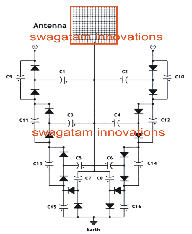
Parts List
All Diodes are 1N4148
C1---C8 = 0.22uF/100V mylar
C9----C16 = 33uF/25V electrolytic
Improving the Free Energy Device
The following more comprehensive free energy deriving circuit design was forwarded to me by one of interested readers of this blog Mr.Prashanth Dhonde.
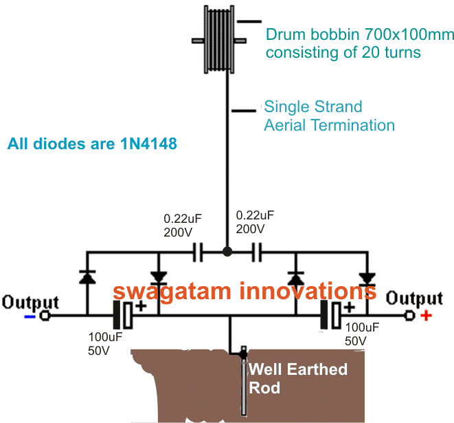
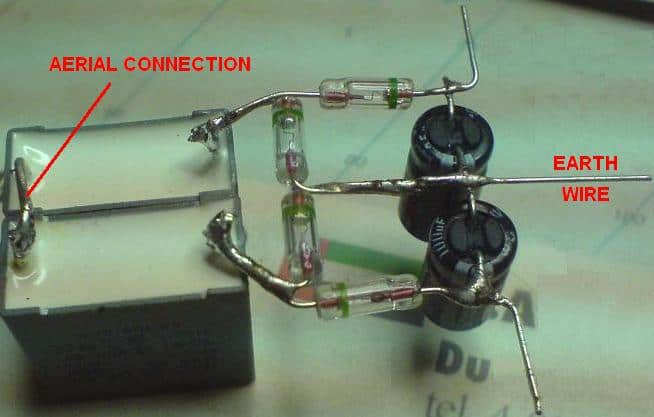
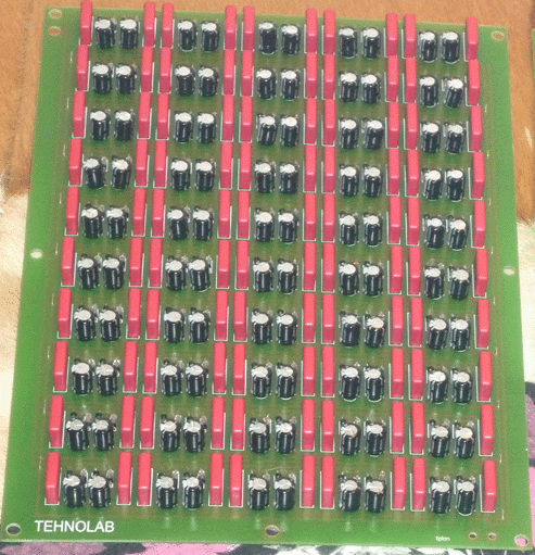
More info on the above design:
Using Fast Recovery Diodes
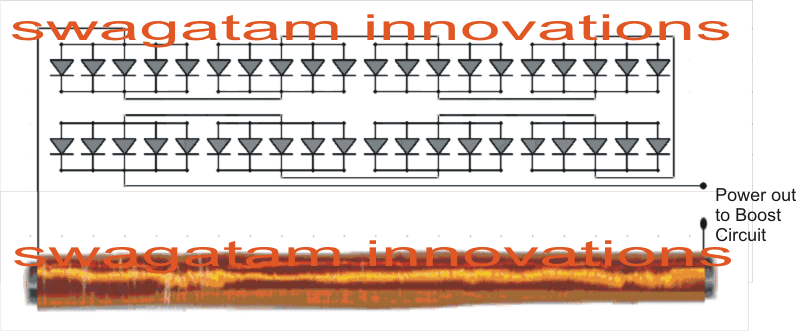
In order to generate more electricity, it is possible by stepping up with more diodes. To make it work properly, the type of diodes and the construction of antenna play a crucial role.
To begin with this process, let us first start setting up the antenna. In order to set an antenna properly, there are some key issues to consider.
An antenna should be made of Ferrite and a height of 30 inch rod is an ideal option to setup the antenna for receiving radio waves.
In regard to diodes, the Geranium the lowest loss diodes and a low breakdown junction voltage of ~ 0.2 - 0.4 Volts is ideal, in case you are unable to find the you may use the regular 1N4148, would just work.
A radio wave gets intercepted in areas with higher concentration and traffic congestion. In this kind of situation it is seen that each diode can pull around 30mV.



Questions & Answers
Hi dear sir,
Can you please provide us high power led driver's all wattage circuit digram
my email. id is swapnilsinalkar@rediffmail.com
Hi Shiv,
You can try the following design:
https://www.homemade-circuits.com/2013/06/universal-high-watt-led-current-limiter.html
Use LM196 for the IC if the requirement is upto 10amps.
hi sir!!!
1. On the last picture, can you give me the schematic diagram?
thanks in advance!!!!
it's the same as the second diagram, just add many of them in parallel.
Hi sir,
I found this link:
frenergy.ca/tapping-into-200-volts-positive-of-free-unlimited-and-unmetered-pure-electrical-energy.html
On this design, frenergy.ca/wp-content/uploads/2013/05/pyramid-flux-capacitor.bmp
what should be the proper capacitor/diodes to use? or any suggestions for this.
Thank you.
Hi Raymund,
The blue cap is 0.0002uF/5000V
The electrolytic cap looks like a 22uF/100V
The diodes could be 1N4148 or BAT30
Do you think 150 feet antenna is practical??
One of the best circuits ever seen. If I use any voltage booster IC(output adjustable one) from National Semiconductor or Texas Instruments and configure it for lets say 6V then if the voltage at the input increases or decreases will I get 6V at the output? If the output changes will the current change or voltage will change. Can I use 1N4007 diodes instead of 4148, 1N4007 is used for rectiication but whats the main difference between the two.
Thanks! I don't think ICs will work here.
1N4007 cannot be used since they are not specified for high speed detection. 1N4148 react much faster compared to 1N4007.
what about out put voltage??? and anyone make this circuit????is this working…Pls tell
hi,
I am looking for an advanced electronic based project on changing weather and climate. It could be and new type measuring device or analysing device using electronics. Measuring weather attributes like temperature, daily sun shine hours, humidity, wind,
precipitation, etc will do. please please tell me if you have any one, even from outside your website. Iam a 9th grader, and i want to take my project to the national level.please give me the link of the project you know or tell me yourself about any project. It would be an great pleasure.
Hi, this could be a complicated design and would need microcontrollers, presently I do not have an appropriate info regarding the subject, if I happen to come across one I'll surely let you know about it.
Thanks!
hi,
I have microcontroller, currently i have atmega 16 and I program with a software called bascom AVR and then compile it and then feed the program with ponyprog 2000 software, using serial port. Please send me the project with microcontroller.
presently I do not have an appropriate info regarding the subject, if I happen to come across one I'll surely let you know about it.
thanks,
but please try to get that within a month. It would be a great pleasure. I have to present it soon.
again thanks,
with regards.
I'll try my best. Thanks
Eng. Swagatam please I need a simple circuit that can reduce 12v/60Ah to 12v/20……25AH for my homemade inverter. thank you.
mawuli, if your inverter is rated to work with a 12V supply you can comfortably use the 12V/60AH or any higher AH battery without worrying…unless the voltage is increased AH will not cause any harm to the inverter.
thank you Eng, Swagatam, but the reason why i need this solution is because the battery turns to burn the components and the jumpers on the circuit board.
Here is the link to the circuit i built.. https://drive.google.com/file/d/0B15SzCeSV14XekxNMEV6dl9YY2c/edit?usp=sharing
the image is not opening,
anyway, check the condition without any load…. if still it starts burning would indicate a malfunction in the unit.
unless the voltage is increased AH will not cause any harm to the inverter.
please Eng. Swagatam can you also sadjust a simple inverter circuit diagram the can power electronics and inductive load. thank you
sorry for bordering you.
you can try any 4047 based inverter design, and add a 0.22uF/400V capacitor at the output of the inverter….. this will fulfill your requirement reasonably.
Thank you Eng. Swagatam I appreciate what your help may God richly bless you.
Dear
Swagatam, please i want a circuit that will changeover between two
batteries for an inverter while the strong battery is powering the
inverter, the weak one is bieng charged automatical by a charger
connected to the inverter…. Please I want to know if it is possible
thank you in advance.
Dear Emmanual,
If you have a low battery indicator in your existing inverter then you could probably try the following design:
https://www.homemade-circuits.com/2012/11/automatic-dual-battery-changeover-relay.html
thank
you for your quick respond, but the inverter am having is a homemade
555 squarewave inverter I made following some of your post and it does
not have low battery indicator, so if you could please help me with a
simple circuit on that so that I can continue from the previous solution
circuit you gave.thank you once again.
Dear
Swagatam
another little confusion is the kind of charger circuit I will need in
charging the dual configuration setup of the batteries, because each of
the batteries am going to use have a high "AH" 12v 100AH and 12v 120AH.
Meaning do I use a single charger or a split charger type.thanks you
once more.
Dear Emmanuel,
A split charger would be preferable, you can build the following design, it is supposed to charge the batteries in a split manner by selecting the battery according to their charge levels:
https://www.homemade-circuits.com/2014/05/twin-or-split-battery-charger-circuit.html
Thank
you Mr. Swagatam… I wl post you the images when and am done and I wl
also let you know when I face any difficulties…thank you once again.
Mr.
Swagatam, and also do I have to combine the two circuit diagrams which
is the dual battery changerover and the split charger? Thank you.
Hi Emmanuel, the last circuit link above will changeover from one battery to the other, so any other circuit won't be required.
thank you Mr. Swagatam
I appreciate your kindness.
Is this inspired by Tesla's Generator?
yes that's right
I have completed the circuit and it works great, but in the bottom picture there are 50 circuits. Any idea if they are connected in series or in parallel? I have tried series to increase the voltage and it keeps decreasing rather than increasing. Any idea how you can hook this circuit up in series?
That's great and interetsing, because most people have a skeptical view about such concepts,
in the bottom image the configurations are in parallel in order to increase current gain and the overall power of the output….it could be done in parallel first and then those parallel strings could be further put in series for getting a sustained boosted voltage
Hi sir !!
Could you please tell the output form, i mean dc or ac and if ac so in which waveform.
Thanks !
Hi sarib, the output will be DC since it would be from the capacitor's stored energy which is always DC
dear sir pls tellme swg of wire its length r whitch type antena will be useable to make this circuit
dear prasanna, you can use any standard flexible wire for it which we normally use in our home wiring. …….1/18 could be tried
Sir can you suggest me a circuit in which first we charge capacitors with 12v then these capacitors give accurate 12 or 11v just for 5 or 10sec
Syed for this you may have to employ huge caapcitor may be upto 10000uF, it will also depend on the discharge rate (mamps) of your application.
Thanks
swagatam i am going to do this project.if i start did i get output .what type of material should be used for antenna
CJ, actually I have not yet tested this circuit, so I am not sure abut the results, however many have tested and have been successful in getting reasonable outputs….
Sir 0.22uf capacitor is not available in my city can you suggest me equivalent. And if i connect a 20ma led with one circuit then does it glow or burn out.
My home is on 2nd floor then the antenna is necessary or not..i means that i will use a shorter anntena or iron rod
Hi Syed, I have not yet tried this practically so cannot say about the results, but an LED will not burn I think, because the setup may not be capable of generating that much power.
0.22uF is not acritical value, you can any other capacitor with nearby values.
antenna is a must and needs to be included no matter on which floor you are, without antenna the circuit may not produce the intended outputs
I tried making the simpler circuit above some years back after seeing it on you tube charging a handphone, it failed to work, not sure if its because of failed components or because it simply doesn't work
the output could be too trivial to notice….perhaps many such circuits needs to be connected in parallel to achieve anything that might be worth considering..
anyone trying to make this circuit will also have to be extra sure to get genuine germanium diodes which have low forward voltage and careful when soldering because they are very sensitive and easily damaged..