For measuring high inductance like 100H, the bridge we use is: James Clerk Maxwell Bridge which people also call Maxwell Inductance-Capacitance Bridge. It is made for medium to high Q inductors but when the inductance is large then it still behaves nicely, so people mostly prefer this one.
Audio/Video Representation
Basic Concept
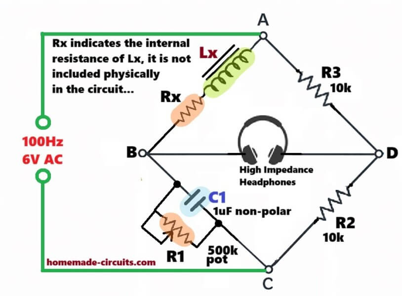
Basic idea of the bridge is simple, it has four arms as shown in the following diagram, with the respective L, C, R components arranged in the bridge format....
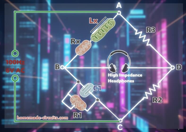
As shown arm one has the unknown inductor Lx in series with its own resistance Rx, which is always there since wire has resistance.
Arm two has standard capacitor C1 in parallel with resistor R1, which we adjust slowly when we try to get balance.
Arm three is just non inductive resistor R2.
Arm four is non inductive resistor R3.
AC supply we apply across one diagonal, and if we do that then across the other diagonal we connect null detector, maybe headphone or AC millivoltmeter, then we listen or watch for minimum sound or voltage.
Balance condition is straight.
Lx = R2 × R3 × C1
Rx = (R2 × R3) / R1
Regarding the Components
So here Lx does not depend on frequency, which is good because if frequency shifts then reading does not dance around.
Now for measuring high inductance values such as up to 100H, which is very big inductance, we have to be careful.
Use low frequency AC source, around 50 hertz to 1 kilohertz, because if frequency is high then reactance becomes too large and then things get messy.
Use good quality polypropylene capacitor for C1, since leakage or drift will disturb balance, then we will keep adjusting again and again.
R2 and R3 should be precision resistors, because if they wander then calculation will wander.
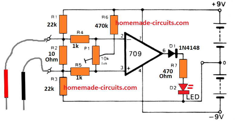
For null detection, use small audio amplifier with headphones, since when balance comes then sound dips very clearly.
For 100H you may need C1 around one microfarad to ten microfarad, and R2, R3 in higher ohmic range, maybe ten kilo ohm to hundred kilo ohm adjustable, so we get workable numbers.
Now here is the practical problem, 100H is very large, usually such coils have high resistance, low Q, and when Q is low then balancing becomes slow and dull, the null is not sharp.
In that case, if balancing becomes frustrating then sometimes Hay’s bridge works better, so we shift method.
Example Design with Calculations
Let us design the circuit properly for Lx = 100H using the Maxwell inductance-capacitance bridge, since we want something practical...
Balance formula is:
Lx = R2 × R3 × C1
So now we want:
100 = R2 × R3 × C1
Step one, capacitor first, because that is the part whch decides everything later. For 100H which is big, we should not pick tiny C1, otherwise resistors might go crazy high, which we do not want, so let us choose something sensible.
Let us take:
C1 = 1uF, good polypropylene type and stable one.
Now we put it in the formula.
100 = R2 × R3 × 1e-6
- So then,
- R2 × R3 = 100 / 1e-6
- Which gives,
- R2 × R3 = 100,000,000
- So basically,
- R2 × R3 = 100M
Now since we do not want to complicate things, simplest way is to keep them equal, R2 = R3, makes things clean enough, right?.
So now,
- R2² = 100,000,000
- R2 = √100,000,000
- R2 = 10,000 ohms
- So now we keep:
- R2 = 10k
R3 = 10k
These look quite normal values, easy to get...
If we check once, then:
10,000 × 10,000 × 1e-6 = 100H
So yes, that part fits correctly.
Now let us think about R1, because that balances Rx.
- Formula says:
- Rx = (R2 × R3) / R1
We already know R2 × R3 = 100M, so:
Rx = 100,000,000 / R1
If coil resistance is around 500 ohms, then we plug that in.
- 500 = 100,000,000 / R1
- Then R1 comes roughly 200k.
So better to keep some adjustment range, not fixed value, since coil may not be exact 500 ohms, so practical choice will be:
R1 = 100k to 500k potentiometer
That gives room to balance properly when we tweak.
So now final set looks like this.
- C1 = 1uF polypropylene low ESR
- R2 = 10k metal film one percent
- R3 = 10k metal film one percent
- R1 = 100k to 500k variable pot
AC source we keep somewhere 100Hz to 500Hz, do not go too high, since at high frequency bridge might behaves differently.
The detector can be simple headphone, of around 60 to 100 ohm impedance...
Why do we show Rx in series with Lx
See bro, when we write:
Arm AB = Lx in series with Rx
We are not adding some new resistor from outside, no. We are only showing what is already hiding there inside the coil.
Every real inductor, since it is wound with copper wire, so it will have some resistance. Also core losses are there, which we cannot ignore. So electrically it behaves like Lx in series with its own winding resistance Rx.
We do not go and add Rx separately. It is already inside the coil. We only show it in the diagram that way so the math makes sense when we balance the bridge. That is all.
About R1 in parallel with C1
This one however is not imaginary. This must be added physically.
In a Maxwell bridge, Arm BC = R1 in parallel with C1. That RC part is placed there on purpose.
Since the coil impedance is Z = Rx + jωL, then the bridge must cancel both parts. The real part which is Rx and the imaginary part which is jωL.
If you only use a capacitor, then you can balance inductance but not resistance. If you remove R1 then Rx will not balance properly.
So C1 handles the inductive side. R1 handles the resistive side, therefore both are needed.
And yes, you must actually connect R1 in parallel with C1 across the same two nodes. This is not symbolic but real hardware.
Now why not just one capacitor
Because the inductor has two parts inside it. One resistive, one reactive. Since there are two parts, then opposite arm also needs two parts, otherwise balance will not happen.
So practically what you will have is simple.
- Arm AB, only the actual coil. Do not add extra Rx, that is already there inside.
- Arm BC, connect one capacitor C1 and one variable resistor R1 in parallel. Both across same points.
- Arm CD, R2 only.
- Arm DA, R3 only.
So final thing is this. Rx is internal to coil. R1 and C1 must be physically added. That parallel RC arm is necessary, otherwise the bridge will not balance properly.