As the name suggests frequency to voltage converters are devices that convert a varying frequency input into a correspondingly varying output voltage levels.
Here we study three easy yet advanced designs using IC 4151, IC VFC32 and IC LM2907.
1) Using IC 4151
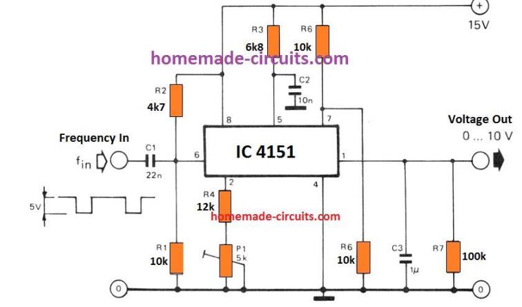
This frequency voltage converter circuit using IC 4151 is characterized by its highly linear conversion ratio. With the indicated part values the conversion ratio of the circuit can be expected to be around 1 V/kHz.
When a DC voltage is used at the input having 0 Hz frequency, the output generates a corresponding voltage of 0 V. The conversion ratio at the output is never affected by the duty cycle of the input square ave frequency.
But, if a sine wave frequency is applied at the input, in that situation the signal must be passed through a Schmitt trigger before introducing it to the IC 4151 input.
If you are interested to have a different conversion ratio you may calculate it using the following formula:
V(out) / f(in) = R3 x R7 x C2 / 0.486(R4 + P1) x [V/Hz]
T1 = 1.1 x R3 x C2
The circuit can even be coupled to the output of a voltage to frequency converter and used as a way of sending DC signals across extended cable connection without the issues of cable resistance attenuating the signal.
2) Using the VFC32 Configuration
The previous post explained a simple single chip voltage to frequency converter circuit using the IC VFC32, here I have explained how the same IC could be used for achieving an opposite frequency to voltage converter circuit application.
The figure below depicts another standard VFC32 configuration which enables it to work as a frequency to voltage converter circuit.
The input stage formed by the capacitive network of C3, R6 and R7 make the comparator input compatible with all 5V logic triggers.The comparator in turn toggles the associated one-shot stage on every falling edge of the fed frequency input pulses.
Circuit Diagram
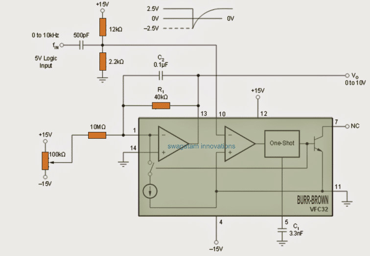
The threshold reference input set for the detector comparator is around –0.7V. In case where the frequency inputs may be lower than 5V, the potential divider network R6/R7 can be appropriately adjusted for changing the reference level and for enabling proper detection of the low level frequency inputs by the opamp.
As shown in the graph in the previous article, the C1 value may be selected depending upon the full scale range of the frequency input triggers.
C2 becomes responsible for filtering and smoothing the output voltage waveform, bigger values of C2 help to achieve better control over voltage ripples across the generated output, but the response is sluggish to rapidly varying input frequencies, whereas smaller values of C2 cause poor filtration but offer quick response and adjustment with the fast changing input frequencies.
R1 value could be tweaked for achieving a customized full scale deflection output voltage range with reference to a given full scale input frequency range.
How the Frequency to Voltage Converter Circuit Works
The basic operation of the proposed frequency to voltage converter circuit is based of a charge-and-balance theory. The input signal frequency is calculated to be conforming the expression V)(in) / R1, and this value is processed by the relevant IC opamp through integration with the aid of C2. The result of this integration gives rise to a falling ramp integration output voltage.
While the above takes place, the subsequent one-shot stage gets triggered, connecting the 1mA reference current with the integrator input in the course of the one-shot operation.
This in turn flips the output ramp response and causes it to climb upward, this continues while the one-shot is ON, and as soon as its period elapses the ramp yet again is forced to change its direction and causes to revert to the downward falling pattern.
Calculating the Frequency
The above oscillating response process enables a sustained balance of charge (average current) across the input signal current and the reference current, which is solved with the following equation:
I(in) = IR (ave)
V(in) / R1 = fo tos
(1ma)
Where fo is the frequency at the outputt is the one-shot period = 7500 C1 (Frarads)
The values for R1 and C1 are appropriately selected so as to result a 25% duty cycle on full-scale output frequency range. For FSD which may be above 200kHz, the recommended values would generate around 50% duty cycle.
Application Hints:
The best possible application area for the above explained frequency to voltage converter circuit is where the requirement demands a translation of a frequency data into a voltage data.
For example this circuit can be used in tachometers, and for measuring speeds of motors in voltage ranges.
This circuit can be thus used for making simple speedometers for 2 wheelers including bicycles etc.
The discussed IC can be also used for achieving simple, inexpensive yet accurate frequency meters at home, using voltmeters for reading the output conversion.
3) Using IC LM2917
This is another excellent IC series which can be used for a multitude of different circuit applications. Basically it's a frequency to voltage converter (tachometer) IC with many interesting features. I have explained more.
Main Electrical Specifications
The main features of the IC LM2907 ad LM2917 are underlined as follows:
- Input tachometer pin which is referenced to ground can be directly made compatible with all kinds of magnetic pick ups having a varying reluctance.
- The output pin is linked with an internally set common collector transistor which is able to sink upto 50mA. This can operate even a relay or a solenoid directly without external buffer transistors, LEDs and lamps can also be integrated with the output including, and of course can be sourced to CMOS inputs.
- The chip can double low ripple frequencies.
- The tachometer inputs has built-in hysteresis.
- Ground referenced tachometer input is fully protected against input frequency swings exceeding the supply voltage of the IC or negative potential below zero.
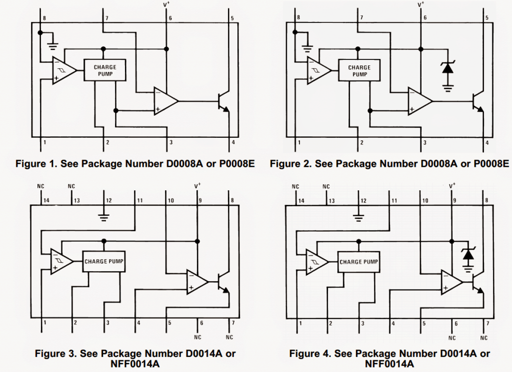
The pinouts details of the various available packages of the IC LM2907 and LM2917 can be witnessed in the below given images:
The main application areas of this IC are:
- Speed Sensing: It can used for sensing a rotational speed or the rate of a moving element
- Frequency Converters: For converting frequency into linearly varying potential difference
- Vibration based touch switch sensors
Automotive
The chip becomes specially useful in the automotive field, as given under:
- Speedometers: In vehicles for measuring speeds
- Breaker Point Dwell Meters: Also a vehicle engine related measuring instrument application.
- Handy Tachometer: The chip can be used for making handheld tachometers.
- Speed Controllers: The device can be applied in speed control or speed governing instruments
- Other interesting applications of LM2907/LM2917 IC incude: cruise control, automotive door lock control, clutch control, horn control.
Absolute maximum ratings
(meaning the ratings which mustn't exceeded, of the IC are)
- Supply voltage = 28V
- Supply current = 25mA
- Internal transistor collector voltage = 28V
- Differential tachomter input voltage = 28V
- Input voltage range = +/-28V
- Power dissipation = 1200 to 1500 mW
Other electrical Parameters
Voltage gain = 200V/mV
Output Sink current = 40 to 50mA
Striking features and advantages of this IC
- The output does not respond to zero frequencies, and produces zero voltage at the output as well.
- The output volatge can be simply calculated using the formula: VOUT = fIN × VCC × Rx × Cx
- A simple RC network decides the frequency doubling feature of the IC.
- An on-chip zener clamp produces a regulated and stabilized frequency to voltage or current conversion (only in LM2917s)
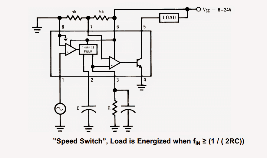
A typical connection diagram of the IC LM2907/LM2917 is shown below:
Using IC LM331
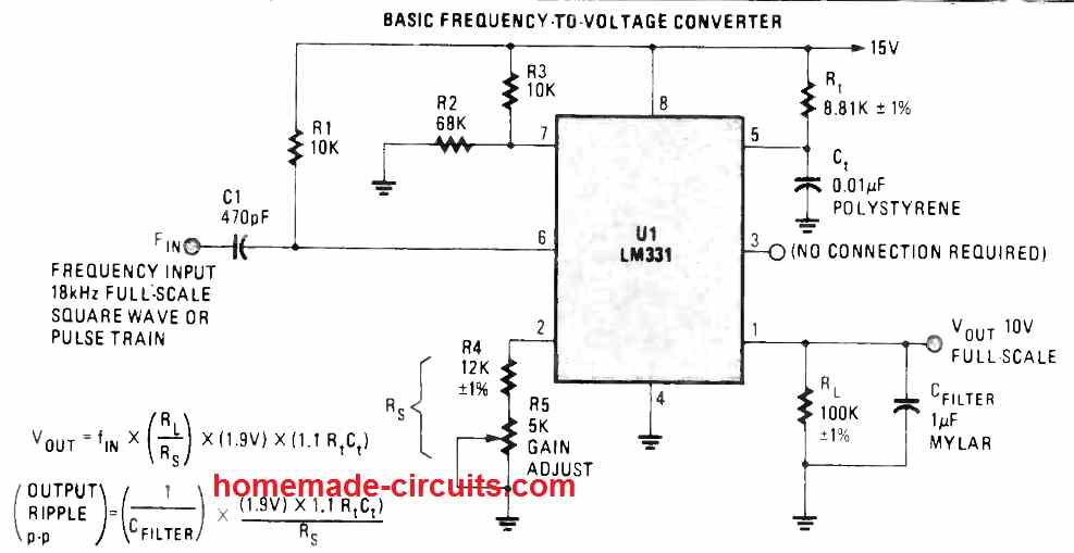
Another simple frequency to voltage converter can be seen in the above circuit diagram, using a single IC LM331.
Here the Vout can be calculated using the following calculations:
Vout = fIN x (RL/RS) x (1.9V) x (1.1RtCt)
For more info, you can refer to this article


Comments
Thanks a ton for your fast replies. I need a bit more output per hz for the LM2907 if I stepped up C1 to .022uF I would get 2.2 volts out for the same 67 hz right?
Thank you very much. If you have calculated the results using the formula VOUT = fIN × VCC × Rx × Cx then yes it is correct.
Hello, for reference would this circuit work with a square wave +12V on the input? I want to be able to go back and forth between reluctor and +12V square wave on the input for my tachometer.
Hello, yes a 12V square wave input can be used with these circuit for getting an equivalent DC at the output.
Thank you very very good
Of iran
Then can we convert high voltages into the frequency in similar way?