While experimenting with a 300V DC to 220V AC inverter circuit, I noticed a strange overunity phenomenon which appeared to be like the generation of free energy from the inverter transformer.
Recently while experimenting with a high voltage converter circuit, I was quite astonished to see a strange overunity kind of occurrence wherein the inverter transformer output seemed to be generating more power than it was being supplied.
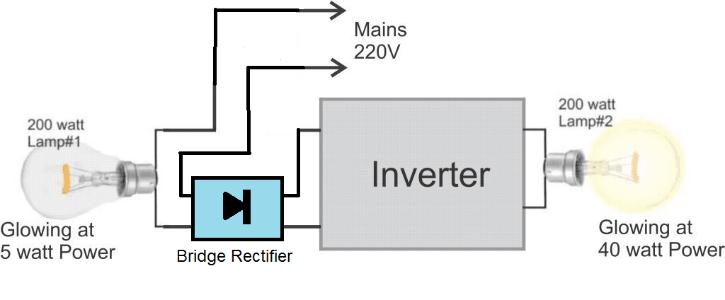
The entire set up can be witnessed in the following diagram:
Block Diagram
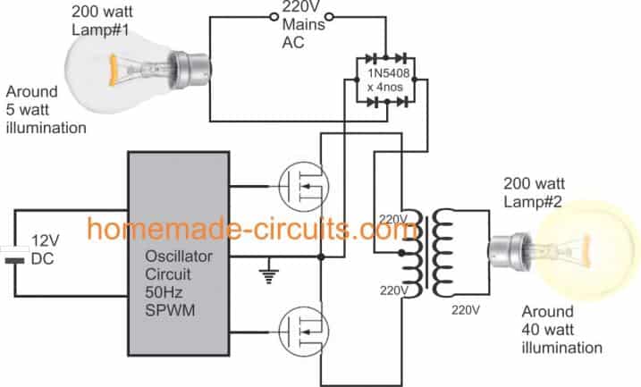
Connection Diagram
Is this Free Energy from an Inverter
In the above set up we can see a very common center tap inverter topology, wherein the transformer center tap is connected with the positive input from the supply, while the two outer ends are connected with the drains of switching mosfets.
The gates of the mosfets are switched with an SPWM 50 Hz oscillating frequency from a 12V DC oscillator stage. The oscillator stage is powered from a external 12V DC battery.
The battery here, is only associated with the oscillator stage, and has nothing to do with the transformer power stage.
The actual power to the inverter is introduced from the mains 220V socket after appropriately rectifying it through a bridge rectifier network using 1N5408 diodes.
To ensure that in case of an accidental mistake in the connections nothing goes into smokes, I decided to connect a 200 watt incandescent bulb in series with the input mains supply during the initial testing of the circuit. This bulb can be seen as Lamp#1 attached in series with the input 220V supply.
After this, I switched ON the 220V mains power for initializing the inverter operations.
I was happy to see that the inverter started working without any issues. However since there was no load connected with the transformer secondary, I was still not sure about the results and regarding the actual performance of the inverer design.
Therefore to test this I connected another 200 watt bulb having exactly similar specifications to the Lamp#1 with the secondary of the transformer.
Witnessing the Overunity
I switched on the mains once again, and was quite amazed to see that the Lamp#2 connected at the transformer secondary switched ON and illuminated with a relatively higher brightness compared to the Lamp#1, which hardly showed any illumination on it.
Lamp#2 was glowing with around 40 watt illumination while the Lamp#1 was barely glowing at around 5 watt illumination.
Since all the power to the transformer was being delivered through Lamp#1, the power sharing should have been perfectly equal across the two bulbs, meaning the illumination on both the bulbs should have been equal, but here the conditions did not seem to be following this rule.
This seemed baffling to me, and I am still struggling to find the answer regarding how the bulb connected with the inverter could produce 6 to 8 times more illumination than the series bulb which appeared to be supplying much less power to the inverter?
From the situation it seems free energy is being created from the inverter with an overunity of 400 to 800%, something that certainly deserves a deeper investigation.
Without the Inverter Circuit, Power Distribution becomes Equal
The following video proves that normally resistive loads having equal ratings will share and divide equal power across them. The video shows how the two 200 watt bulbs produced identical illumination (100 watt each) without the inverter circuit involved.
Second Video Confirmation
I tried the experiment one more time, just to confirm whether the results were consistent or not, and fortunately the experiment yet again proved the above explained overunity occurrence, leaving no doubts regarding the perceived outcomes. Here's the video for you all to watch.


Comments
Oh really???? thank you for enlightening!!!
The illumination is a direct indication of power, the bulb2 is showing 8 times more power output than bulb1 despite of having exactly equal specs. There has to be some theoretical and logical explanation first….
Hello, I believe in free energy. I have a welding inverter at home, and many fuses 25A, to replace the electrical panel. Whenever I connect a fuse at the output of the inverter, it burns. The fuse does not burn from the electrical panel even when I put the inverter output 2, 3, ….. 10 fuses connected in parallel. The same thing happens with other inverters or welding transformers. Are all transformers or inverters on Earth gain free energy? Fuse 25A from the electrical panel is not connected in series with the fuses at the output of the inverter, as well as with your bulbs. Your less light bulb is a series circuit with the mayor of the transformer which has a higher resistance. At the bulb terminals measure 20V 0.9A and at the inverter terminals 200V 0.9A
Hi, I appreciate your interest in the field of free energy. I too hope the concept is true, however since I haven’t checked it with advanced equipment, I can’t verify the details at this moment….I hope I will be able to crack it sometime in the near future.
Hi, Swag.
Thanks for sharing this effect. I achieved this effect in my own experiments, which are in fact an attempt at free energy. In my setup I would charge a big capacitor bank, through a lamp, because the inrush current is too high, which is similar use of your limiting lamp. As capacitors charge, the voltage difference with the grid lowers, so current drops and eventually become zero. Now what is interesting is when I start consuming small impulses from the capacitor bank, they have available both high voltage and high amperage, while to the grid, the capacitor bank presents a small voltage difference and small current is flowing in order to compensate the charge in the capacitors. This way I could light my output lamp brighter than the input lamp. Lets say I consume pulses that drop the capacitor bank from 300V to 250V and output lamp is driven at full power with a PWM and at the same time the input lamp is driven with only 50 volts. This is your effect and it is working and very interesting. Is it overunity? .. IDK, the thing is that capacitors draw a lot of power (I have watt meter) and they consume the most when they charge this top range 250-300V, so I guess no overunity, at least in my case.
Now what I see in this schematic is a cool arrangement, where you pulse 1/2 of the primary, the load on the secondary should cause the primary to draw more but at the same time your primary is also turning into an auto transformer, which is probably opposing the incoming grid current and this effect is very interesting and worth examining. If this is true 440V might be present on the primary, somehow flowing through the mosfet body diodes, both opposing the grid and powering the second lamp. I am in no way trying to dismiss your effect because it is with inductors, quite the opposite, I am very excited about it. Please take a look at Tariel Kapanadze and his overunity device which is a mistery to this day. It is powering few kilowatts load and yet consuming very little power and it is self powering. Your discovery might be an important step at understanding his setup and effect.
That sounds interesting Ivan, I appreciate your inputs very much. I’ll surely investigate the Tariel Kapanadze theory as suggested by you…thanks so much and please keep up the good work!
A most interesting and encouraging result. Others have also noticed unusual behaviour from similar circuit configurations. I do have some theories as to what may be happening with your controversial circuit. I am hoping to run some of my own experiments (similar but not the same) to sort out my pet theories that go back many months. Present circumstances make the project difficult.
Polite Warning: This is a very sensitive subject, as those who prefer ‘orthodoxy’ hate the very idea of ‘overunity’! Please tread carefully.
Thanks for the interesting feedback!
I think with 2 clamp meters we can justify real consumption….
you connect bulb at main ac in series which is working as normal wire without any resistance, that why main ac bulb is not glowing more than other bulb… …. and the other bulb normally connected parallel …
Hello! Glad to meet you. Am Eddie from Africa Uganda Earth! I have some simple question related to your overunity inverter output! How much power is used to excit a generator rotor(field)? That’s our input, right? How much power do we get from the stator coils ? A very big ratio to the rotor input! Iron cores magnify the magnetism beyond our input and that’s why I hope we can have free energy or overunity. Am trying something where by am exciting a field winding of a tiger t950 generator with an AC and the stator winding is able to do some work but since I have no AC ammeter, I can’t spell out how much am consuming and producing the rotor and stator windings respectively but the out put voltage in the stator is a half of the input because this is a two pole stator so it has 2gaps which are not extending up to the stator. I believe there’s free energy trust and am trying it bro . Love you all
Hi, sorry I have no idea about it!
I think the inverter is acting as a boost converter
Let’s assume that Lamp1 and Lamp2 are of equal resistive impedance. We can even put an approximate calculated value. 220 * 220 V / 200 W = 242 ohms resistive. If we were to put the 2 lamps in series on a 220 V source we would end up with a total power consumption of about ( 220*220/484 = 100) 100 Watts. In this particular case it would be correct to state that the total power consumption is equally distributed between the two lamps. No lost of power anywhere else than the two lamps, nor any energy creation. The total power in equal the total power out.
In the above case Lamp 2 is said to be outputting 40 watts (assuming that its impedance is not changed for sake of simplification, which actually is not the case) the output voltage of this converter would be (SQRT(40*242) = 98 ) 98 Volts. Same calculation for Lamp1 (SQRT(5*242) = 35 ) 35 Volts. This means that the total energy spent for illuminating both lamps would be a total of (5+40=45) 45 watts. Add to this the lost energy for transforming the electrical energy ( assume 10 watts for sake of explanation ), Total energy consumption from the circuit and the two lamps would be approximately 55 watts.
Now, why is Lamp2 illuminate more than Lamp1 ? is the real question. And the answer will teach us that there is no extra energy created here.
Let’s assume a modified case from the first exposed in the beginning of this attempted explanation. ie: Lamp1 is of impedance 80 ohms, the converter circuit is assumed to be replaced by a resistance of impedance 160 ohms, and Lamp2 is of impedance 640 ohms. This series configuration circuit would create a situation similar as the “Energy Creation” circuit discussed here. ie: all 3 resistances would have an equivalent energy consumption and both lamps would exhibit the same apparent illumination power of respectively 5 watts and 40 watts. The converter part (replaced by a fictitious resistor) would consume the remaining 10 watts. We just proved that it is possible to have 3 devices in series that Could consume the same current and spend different power losses.
We also demonstrated that the reason why Lamp2 is more illuminated than Lamp1 is simply a question of impedance. I this case of interest it become obvious that the converter circuit is simply acting as an impedance converter which direct more electrical energy into Lamp2 than is consumed in Lamp1.
One could create a similar arrangement with a much simpler circuit. Simply connect one lead of the transformer in series with Lamp1 and plug the whole thing into a 220V source. Connect Lamp2 on the output of the transformer and you will find that Lamp2 will substantially illuminate more than Lamp1. Why? Because the transformer would be acting as an impedance changer for Lamp2. In essence, Lamp2 would exhibit at the primary of the transformer a much higher impedance, hence lowering the available current on Lamp1.
Hello, In your circuit diagram you show a ground symbol on the Sources of the two MOSFETs.
Is that actually an Earth ground connection, or where does that ground connection connect to?
If that is not an Earth ground connection, can you not simply measure the average power being supplied by the AC mains?
Hello Swagatam.
I see. That is interesting. If you measure the average input power from the mains to the transformer, it should help to clarify what is really happening, but it is not necessary to rebuild it since you now recognize that it is related to the transformer.
Best wishes!
Thanks Stan, next time if I happen to assemble the project again, I’ll make sure to test and compare the power, and update the results for sure!
The ground symbol is not the actual round, it’s the common negative line of the oscillator 12V and the mains 220V DC.
Creating the set up once again can be difficult but I will try in near future if possible.
I recently replicated the circuit without using the oscillator circuit, only by feeding the 220V 50Hz directly across 220V side of the transformer, and I got the same results. So it’s the transformer that’s doing the trick basically.
Thank you for the detailed explanation, it just about explains the fact behind this mysterious looking experiment.
The simple experiment suggested by you will work, no doubt, because it’s the transformer that’s doing the trick, not the circuit, the circuit is just an oscillator, which can be replicated with the 50 Hz from the AC itself.
But it is still difficult to simulate how the impedance conversion is able to restrict input current to lamp1 and yet channelize it to lamp2.
No matter how the power may increase, it has to come from somewhere, if it’s coming from mains source then the series load must also get effected. Remember here both the loads are identical and resistive in nature.
basing the schematic diagram, the 220 Vac is just an additional voltage which is converted to Dc voltage by bridge rectifier. The rectified dc must be lower because of the bulb in series. The power dissipated by lamp 1 is not related to the power dissipated by lamp 2 , therefore must not be equal . As the inverter is oscillating to drive the primary winding of the transformer , the rectified DC is just added to the inverter circuit and since the inverter has a DC resistance so it will complete the loop of the added DC supply .
power dissipated by lamp 1 is not related to the power dissipated by lamp 2? so from where the lamp2 is getting the extra power (illumination)?
Hello, it is already January 29, 2019, and as it was now, it is really overunit what you discovered, detail me because it is a good hope for the planet
It seems like it is an overunity from the inverter circuit, but it needs to be investigated further for confirming the results.
Dear Sir,
I am living in Delhi, Is possible you build for me Energy from Inverter with Amazing Overunity kit and send to me and i pay you money for this kit
because i tried but this not working ,so i decided better your build for me and send to delhi and i pay money to you .
please let me know how much i need to pay you as well as how long it will take to send me
Thank you for your interest Sanjay, actually the experiment is still not fully confirmed, therefore it may not be recommended to sell this idea yet. Once I am fully convinced then I may definitely start providing it to the interested users.
Sub_Free Energy from Inverter with Amazing Overunity
Dear Sir,
I made circuit but my builb 1 only bright (series connected to main with bridge) and buld 2 very dim (secondary side of transformer )
I use Square wave ,120HZ , Please help to work like yours
my mail id sanjaysingh201@gmail.com
Thanks
Sanjay
Hi Sanjay, I am myself not sure regarding the exact reason of the mentioned phenomenon, so I won’t be able to suggest much. However I may try the experiment once again , just to check whether or not the experiment is able to sustain the performance over and over again.
Swagatam Ji,
Namaskar.
Kese ho?
SMPS based power supply will also show the same effect.
Take mobile charger or any smps power supply, connect a bulb1 in series into charger input supply. Connect another bulb2 at output . You will see the
Bulb2 is brighter then bulb1.
Devendar ji, I am good, thank you, which type of bulb are you referring to? Remember both the bulbs should be of the same wattage.
Hello Swag,
Thank for the initial response on YT. I am designing a replica circuit and am have some observations:
1) This inverter is neither a step up or step down but a conversion from AC – DC – AC again, which is done via SPWM.
2) This process removes the reactive component after the DC stage, where the signal is a series of modulated pulses within a 10 ms square wave. The signal of which produces a sinewave through the transformer. Is this correct?
My questions are :
1) At what frequency did you choose to phase correct the pwm (in kHZ)? I am wondering if this effect is happening in the higher frequency range ( 100-200kHZ) and you stumbled on a behaviour that may be linked to the transformer rated at only 50hz? Could this be an effect of bEMF generated from phase correction? Could the rest of the in-series AC line simply not ‘see’ much of a load (like a dimmer circuit) and why the bulb 1 is barely lit?
Anyway, answers to frequency of the modulated pulses making up the 50 Hz squarewave and the type of RS transformer would be greatly appreciated. I think this is a very important effect you have found 🙂
Kind regards,
Tivon
Thank you Tivon,
I accidentally came across this phenomenon while trying to test a 300V DC to 600V AC converter concept. Since I did not have an access to a 300V DC I decided to use my AC mains for this, and just to be on the safer side I made sure to have a series bulb, in case something went wrong.
Frankly, I am not sure what may be going on inside the design and how the inverter bulb is able to attain more brightness than the input series bulb.
For the oscillator I used an ordinary IC 555 astable, set to generate a 1kHz frequency. This frequency is supplied to a couple of IC 4017 cascaded dividers, which divide the frequency into two sets of SPWMs at around 55Hz base frequency, which are fed to the respective mosfets and transfromer center tapped winding.
The complete circuit diagram can be found here: https://www.homemade-circuits.com/1500-watt-pwm-sinewave-inverter-circuit/
I am planning to repeat the experiment once again, because I realized that earlier one of the channels of the inverer was probably not working, otherwise we could have seen even more brightness on the bulb#2, I will try it soon and present the results here.
Fantastic update! Many Thanks 🙂
I did the experiment yet again and glad to say that the result was pretty much the same. Surprisingly this time the series bulb was even dimmer and its illumination was hardly noticeable. I’ll upload the video soon.
This time I interchanged two 200 watt bulbs just to make sure that there was no hidden issue with the bulbs and they were exactly similarly rated, and I couldn’t find any issues with the bulb behavior, both ways the results were identical.
Would it possible to connect a watt meter from the wall to see if there is a deviation in the power draw? Also wondering if a phase shift occurred at bulb 1 (reactive)? You could do the by-pass wire again and see if there is a change in the watt meter reading?
yes that would be interesting, however I do not have a wattmeter at the moment, if I buy sometime in future I’d surely check it. I am not sure how a phase shift could help in an overunity to develop, but it may be related to the flyback working conditions
Respected Sir,
This is strange!!!!!
Looks like the LED connected with the inverter terminals is in series with the battery, Right? In such a case, firstly the inverter will not operate at all, and
How is it that you’re applying a direct rectified 325V DC between the common ‘source’ pins tied of both mosfets and the center tap of the transformer?
Wont applying direct mains at these two points on the inverter section harm the inverter instantly?
Again, if noticed in the video clearly, both lamps don’t have a steady glow on them, which means that the mains rectified DC is pulsating, passing into the transformer and this directly has an effect on both lamps flickering.
Can pulsating DC be passed into the rated transformer safely? I’m still confused on what’s happening in the system you prepared.
Let me investigate more clearly…………
Hi Sherwin, thank you for your interest. It seems your questions are not related to free energy, rather regarding the use of 220V as the input and pulsating current.
In the experiment I used a 220-0-220V /110V transformer, and 1000V rated mosfets, and that’s why I could safely apply 220V DC as the input since the components were appropriately rated.
All inverters work by applying pulsating current to the transformer, that’s how inverters are supposed to work, therefore in this experiment too the same principle has been implemented.
I hope it solved your questions, let me know if you have anymore doubts
Yes it must be.
I thing voltage across bulb 1 is less , compared to voltage across bulb 2 .
Have you checked
1. Voltage at bulb 1.
2. voltage at transformer input.
3. voltage at bulb 2
Regards Devendar Jakhar
Can you produce two different light levels on two similarly rated bulbs in series?
Since it is a frequency based circuit voltage/current measurements can be confusing, here illumination itself is enough proof for the mysterious condition
If bulb#2 would be dim and bulb#1 would be bright then it would be useless, because it would mean that the inverter is consuming more power.
But here bulb#1 which is supplying all the power is dim and bulb#2 is bright, that’s the mystery??
Hi dare,
Resonance is good, but you said that without it the transformer will become a current HOG, so that’s not true! Some losses will be obviously there due to harmonics which can be eliminated using resonance filter.
I have already written about resonance in one of my earlier articles:
https://www.homemade-circuits.com/2016/09/designing-induction-heater-circuit.html
Sir. Swagatam, I am giving you theoretical explanation on Resonance in any type of inductor. Rather I have PRACTICALLY tested what I am telling you. I am a Builder so no hogwash words from the blues please.
If you tune any inductor to resonance, it will stop taking current from the source anymore!!!
In other words, when you tune the Secodary to either Natural Resonance or Padded Resonance (Forced/Super Imposed), Lenz would be Negated right away. And when that happens the inductor or Transformer becomes Asymmetrical Transformer.
Do the practical test yourself.
Take an LCR Meter and measure the inductance of a Ferrite Core Secondary side trafo. T
Determine your oscillator frequency which could be 30Khz or more.
Imagine that!!
So please go for it….. RESONANCE!!!!
However, it is best to Inegrate Resonance in any Inverter circuit design. Resonance would keep the Inverter Transformer (when under or no load) from becoming an amperage Hog.
An inverter consumption directly depends on the connected load, when there’s no load the inverter is supposed to consume negligible current, unless there’s some serious fault in the inverter.
The circuit works in the same way even without the capacitor.
The said 105/250VAC Polypropylene Cap
Thanks Dare, which capacitor are you referring to!
Oh it is a relevant Swag. The cap is acting as Resonant ringer.
Your best bet is to get the Transformer to itself to Ring in line with the oscillator frequency.
If the Earth is hanging upon nothing, Resonance keeps it there.
That we all need to immitate to gain Power from Nothin!
Thank you Martin, the mentioned free energy phenomenon was an accidental discovery, when I operated an inverter with 310V DC from mains with a transformer having a rating of 220V-0-220V primary, and 110V secondary. the bulb was connected to the secondary side. I do not have much idea regarding the technical explanation of the outcome of the experiment
I love your posts here from zambia, kindly clear for me on the tranformer, the transformers i can find here in zambia, usually are center taped on the secondary ( out put sided) while the side where the we connect the main usually have only two wires, the common transformers we can salvage from aready existing inverters are usually 220v down to 12 v, so Big man, how do make this circuit with such transformer, and can i use any mosfets such as the 3205, 1010e, thanks in advance, Love from zambia God bless you.
No I am not saying that, I am saying how can two bulbs having identical rating consume different power when they are in series.
If suppose 40 watt is being consumed by bulb#2, this 40 watt must pass through bulb#1, then both must share equal illumination.