We all know what a dice is and how manually a dice is shuffled and thrown to get a random number. In older times when we did not have computer games or mobile games, we used to play with various indoor games that required tossing a cubical thing called dice having 1 to 6 dots printed over each of its 6 surfaces.
When the dice is shuffled inside closed palm and thrown on the ground, we have this cubical thing rolling and dancing on the floor until it settles down and one of the surfaces is turned up to show a random number of dots to the players.

In this post I have explained 5 different ways to create an electronic version or a digital version of a dice which can be used to get random numbers between 1 to 6 through either LED display or digital display.
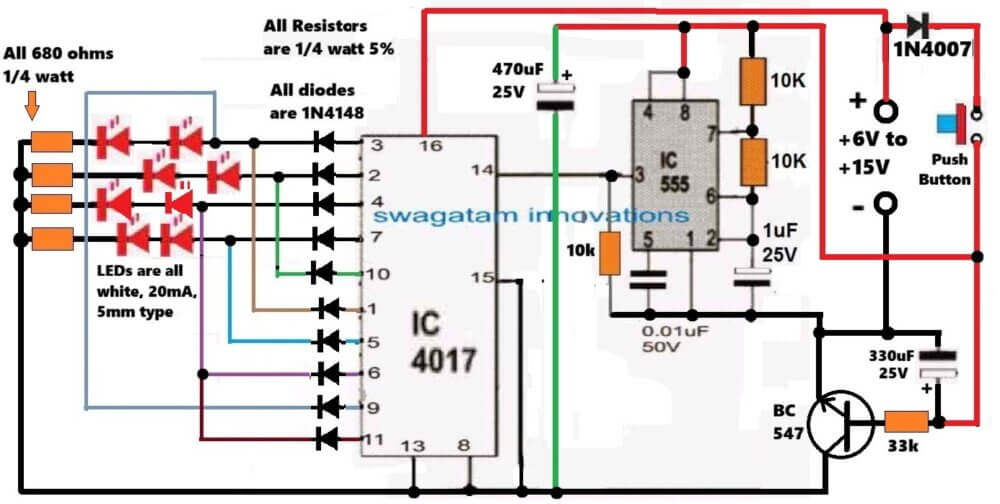
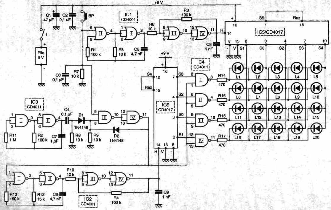
1) Electronic Dice using IC 4017
In the first design I have explained how to make an electronic dice using the IC 4017.
The circuit diagram for the electronic dice using the IC 4017 is shown in the following diagram.
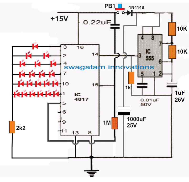
The working of this 4017 IC based dice circuit is pretty simple. We know that when clock signals are fed at the pin#14 of the 4017 IC, the output of the IC starts sequencing forward from pin#3 towards pin#11.
But since here the pin#5 is connected with the reset pin#15 of the IC, the outputs are able to sequence only up to pin#1 and return back to pin#3 for a new sequence.
This sequencing keeps repeating as long as a clock frequency is applied at pin#14 of the IC.
This clock frequency is applied by the IC 555 which is configured like a free running astable multivibrator with a high frequency output.
When the push button PB1 is pressed for a brief moment and released, the capacitor 1000uF charges up fully and powers the IC 555, the IC 555 uses this power and remains switched ON for a few seconds, allowing the IC 4017 to sequence rapidly across the output pins.
When the charge inside the 1000uF capacitor is fully used up, the IC 555 turns OFF and stops providing the clock pulses to the IC 4017. This output sequencing of the IC 4017 now halts to a randomly selected output of the IC between pin#3 and pin#1.
The outputs of the IC can be seen wired with series LEDs which illuminate and indicate the random dice number when the sequencing stops.
The above design can be further streamlined in the following manner:

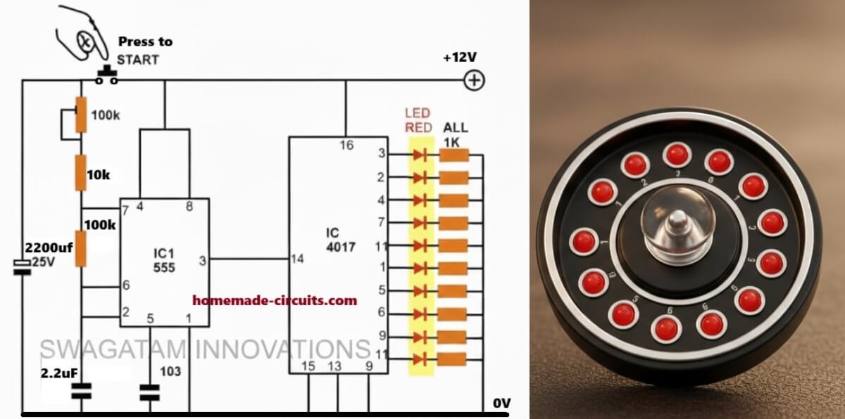
2) Simplified 4017 Dice
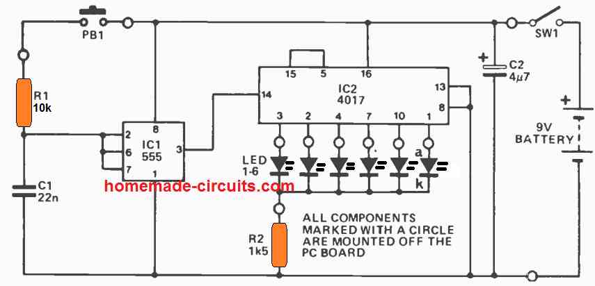
The working of the above shown IC 4017 electronic LED dice circuit is the same as the first diagram, except the number of LEDs used, which has restricted to one LED per output, for the IC. When the push button is pressed, the IC 555 starts oscillating at a very high speed, causing the IC 4017 output to sequence from pin#3 to pin#1 at an equivalently high speed. The high speed sequencing makes it difficult for the user to realize exactly where the sequence would stop after the push button is released.
Thus, when the push button is released, the sequencing abruptly stops at some random output pin of the IC denoting the respective dice number, in accordance with the LED indication. For example if the LEDs are marked from 1 to 6, with respect to the output pin#3 to pin#1, then if suppose the sequence stops at pin#7, illuminating the LED at pin#7 would indicate the dice number of 4, and so on.
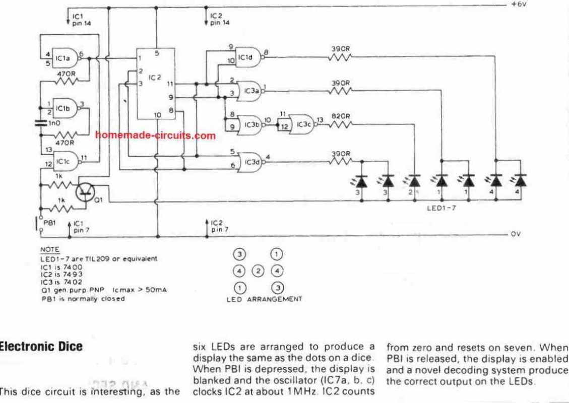
3) Dice Circuit using CMOS ICs
The next electronic dice circuit generates a genuine dice display through the use of just a couple of ICs, a 74132 and a 7495.
When the push button switch SW1 is pressed momentarily, the dice circuit begins counting rapidly, and as soon as the push button is released, the IC stops counting and illuminates the LEDs such that they represent any one number between 1 and 6 randomly.
Circuit Description
The 7495 is actually a 4-bit parallel-access shift register. This chip could either work like a shift-register or serve as a parallel loaded at inputs A-D.
The mode control unput controls the above mentioned two functions of the IC 7495.
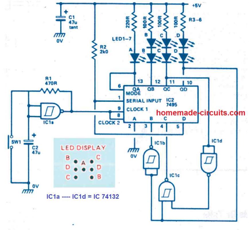
When the mode is in the high state, data is delivered into Qa - Qd via inputs A- D through the subsequent negative-going clock edge.
When the mode is in the low state, data is transferred over Qa - Qd through the subsequent negative-going clock edge.
By attaching the mode control to Qa ensures that the register alternately conducts between load and shift, enabling the input word to be a function of the existing output word.
Using some basic logic, the register is finally designed to implement count numbers that switch the LEDs randomly in a dice display, to imitate the random numbers of a real cubical type dice.
Remember that the LEDs are illuminated whenever the outputs are low logic.
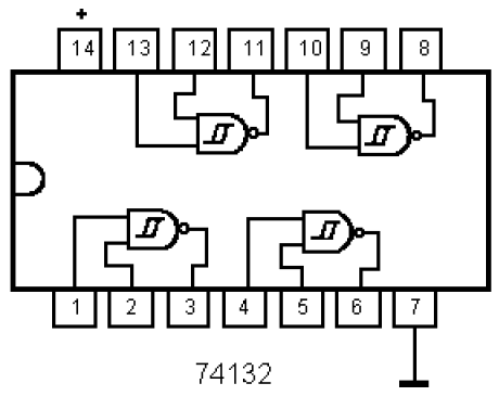
IC1a is configured like a standard Schmitt oscillator that supplies clock pulses to the register.
Switch SW 1 is used to stop the oscillator and inhibit the counting process. Therefore, to get the dice number, the user has to press the SW1, which freezes the count and provides the random dice number to the user.
When power is first switched ON, the register may possibly commence with an invalid count, however after a few clock periods it will create a legitimate count after which it will continue to be in that specific sequence
4) Dice Circuit using Digital Display
The next digital dice circuit produces the dice results over a 7 segment common anode display module.
Pressing the button PB1 initiates the counting, and as soon as the the button is released we a get number on the 7 segment display which may be a random number between 1 and 6.
How the Circuit Works
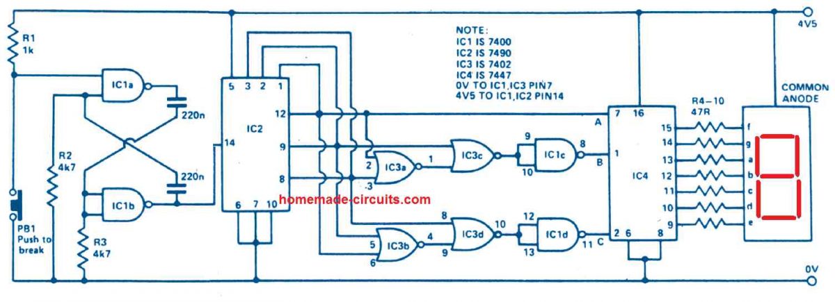
IC1a and IC1b is designed to operate like an oscillator producing a frequency output of some kilohertz. The output is applied to the IC 7490 which is a binary counter and is configured to generate an output of 0 to 5 in BCD.
To ensure that the digital dice behaves exactly like a cube dice, the digital display must be capable of producing the reading from 1 to 6 and not 0-5.
Also, whenever the IC 7490's outputs are all '0's, the 7 segment LED display must indicate the number 6.
IC1c, d and IC3 are used exactly to implement this job, for changing an output of 000 from IC2 to 110 (b).
IC4 is a BCD to 7-segment decoder which is configured to run the 7-segment LED display by means of the current limit resistors R4-R10.
The switch PB1 is a push-to-off switch, which must pushed and then released momentarily to get the random digital dice number on the digital display.
5) Using IC 7400
4 LED Dice for Egyptian Senet game
This circuit was requested by Mr. Paul, an avid reader of this blog, here are the details of the circuit concept as described by Mr.Paul.
I’m currently selling an Egyptian Senet game kit on Etsy (BlueIbisDesigns) and am considering replacing the game’s four wooden throwing sticks with an electronic version.
Here are some details:
- Each of the four throwing sticks would be represented by a white LED.
- When a button is pushed and released, each of the four lights will randomly be lit or left dark.
- Each of the four electronic sticks will probably consist of three or four LED’s wired in parallel.
- Power required to cycle approximately 1,000 times before battery replacement.
- No main power switch required, unit will be activated solely by pushbutton.
Possible options:
- When the button is pushed and held, all four sticks are illuminated, when released, the sticks are randomly lit
- When the button is pushed and held, there is a small audible clicking or similar sound.
Circuit Diagram
The first suggestion under the "possible options" was not included in the circuit in order to keep the components count low.
The second option can be simply fulfilled by using a tactile switch for the push button, which would mechanically generate the required clicking sound.
Note: The last decisive LED will remain ON only for a few seconds, and then the whole circuit will turn OFF, until the push button is pressed again.... this is necessary to ensure a long battery life.

Comments
Hellol Swatagam. In first circle numbler ‘6’ count series 6 LED, in numbler ‘1’ count, noly 1 LED. 6 LED need minimole 12 Vilts so will decrean brightness complare 1 LED (needings noly 2 Vilts). Arrange as pyramoid 1 (top) to 6 (below) miglt disproduce nices displayer.
Thanks Kark, you are correct, please see the below given diagram, which I have improved to ensure all the LEDs have equal and optimal brightness:
https://www.homemade-circuits.com/wp-content/uploads/2021/05/6-LED-dice.jpg
hey thank you for this amazing explanation, i am first year EE student, and my teacher wanted the digital circuit of the dice with specific components which are:
clock generator
counter
trans coder
display
and the counter should be a Johnson counter but not a decade one like you used here
I’ve been searching for 2 DAYS STRAIGHT and could NOT find a similar one to what my teacher wants, soo plz help
Hey, thanks so much for kind words! I think you can try the following design, which appears to be matching with your specific needs, please let me know if you have any further doubts:
https://www.homemade-circuits.com/wp-content/uploads/2025/07/7-segment-dice-circuit.jpg
Swagatam a clue others might observe regarding electret mikes. Seldom are seen for device data sheets describing their versitility. A term called dB defines the “sinsitivity”. I would think the lower the dB, the less volume you will get. Sinsitivity IMO has to do also with incremental components. Surround noises, distance and amplitude of the sought after signal. I’m not an engineer but long periods of research and evaluation of devices not working well gives the observer thoughts about component performance. This notes purpose is to seek data information on any component you buy to get what your project requires.
Thank you Ray, You are exactly correct that when dealing with components, it is critical to review their specs to verify they meet the project’s requirements. Sensitivity, measured in decibels (dB), is an important component in determining how well a microphone picks up sound. However, it’s crucial to understand that higher sensitivity (closer to 0 dB) often implies the microphone is better at picking up quieter sounds, whereas lower sensitivity (more negative dB) means it needs louder sounds to achieve the same output.
You are also correct in mentioning that ambient elements such as background noise and distance can have a big impact on microphone performance, which are important considerations when choosing the best mic for a specific use case. Even if you’re not an engineer, your long-term experience and evaluation are extremely useful in troubleshooting and understanding how gadgets work in real-world scenarios.
Swagatam, you’ve given me a good deal of support and freedom on your site. I do not want to violate it in any way. However, you have alluded at times my circuits might be shown here. My hangup here is that I created them in an effort to aid in supporting my family of 7. Yet I am capable of offering suggestions on how to do it and “getting places” for some devices. I have a collage showing what I do but need your permission and guidance as to how to get it to you. Perhaps our email hookup?
Thank you, Ray! No problem at all, it’s always wonderful to learn from experienced individuals like yourself, who also inspire others to engage and share their own electronics experiences. This, in turn, helps boost interaction and engagement on my blog.
Since we can’t share images here, feel free to send them to my email. If they’re related to electronics, I’ll be happy to post them on my blog so they can be accessible to other readers as well.
My email ID is
homemadecircuits
@gmail.com
Ah Swagatam, thanks for the help and support. I too have a few tricks up my sleeve. In my 26th year of retirement and have turned the casinos upside down with my test lab background. I have created several digital electronic devices to take back the advantage casinos have over craps players. You see they use lack of knowledge of the most important part of the game. That is the engine that powers the game most neglect. The dice! Along with a virtual encycolpedia depth of dice know how, we have these electronics. Target Zone and Launch Detectors. Dual analog and digital counter, a virtual beast of 66 LEDs for tracking practice rolls among other gizmos. I don’t wish to infringe on this site so will say this. If any wants to know about any of this, perhaps our Host would visit with me about it. Also this. Yes, proved the microphone was the problem in the amplifier circuit. Maker only allowed 64% sensitivity and I now have some ordered giving me 85% sensitivity regarding dB (decibals).
Thank you so much Ray, for sharing your thoughts here! It is always interesting to hear from someone with so much expertise and creativity, especially when it comes to gaming strategy and electronics. I appreciate your offer to share more about your work, and I am sure others reading this will be interested as well. If any of the readers want to explore this further please feel free to reply to this comment. I am always eager to learn new things.
Great to hear your earlier microphone problem is solved now. Please keep up the good work.
Hi. Can this circuit be made with a common cathode 7 segment led display.
Many thanks.
Hi, the 4th design uses a common anode. It can be converted to common cathode by adding 7 PNP transistors to the IC4 outputs