• Skip to main content
  • Skip to primary sidebar

Homemade Circuit Projects

Need circuit help? Post them in the comments! I've answered over 50,000!

Blog | Categories | About | Contact | Calculators-online
You are here: Home / Inverter Circuits / Dual A/C Relay Changeover Circuit

DIY Circuits | Learn Basics | Arduino Coding

Dual A/C Relay Changeover Circuit

Last Updated on March 8, 2019 by Swagatam 4 Comments

In this post I have explained a simple relay changeover circuit which may be used for switching a couple of A/Cs or any similar load alternately in order to avoid misuse and save power.

Technical Specifications

Here is the situation:

State: California.

Facility: Church.

The electric rate is greatly influenced by peak usage in any 10 or 15 minute period during the month. So if usage exceeds the threashold value once in the month, the rate for every KWH in the month goes way up.

Concern: We have 2 large airconditioning units. If both are run at the same time we will exceed the threashold power consumption, and trigger the high rate for the entire month. People keep turning on both units whenever they feel too warm with no regard for costs.

Need: A (24V) circuit that works with the A/C thermostats such that: A/C unit 1 turns of/on based on its own (programmable) thermostat; and A/C unit 2 only comes on if 2 conditions are met: a) unit 1 is not running, and b) the thermostat for unit 2 is calling for cooling.

Can you design a simple relay circuit that would disable unit 2 if/when unit 1 is running?

- Lyndon

The Designed and Drawn by: Abu-Hafss

The Design

According to the request:

A/C unit2 ON/OFF switch should stay disabled while or as long as A/C1 is running and in a switched ON position.

The second condition may be ignored since the thermostat of A/C 2 would itself  keep the system switched OFF irrespective of A/C1 condition or the relevant ON/OFF switches.

The above circuit which was designed by one of the dedicated readers of this blog Mr. Abu-Hafss fits the situation perfectly and satisfies the requested need

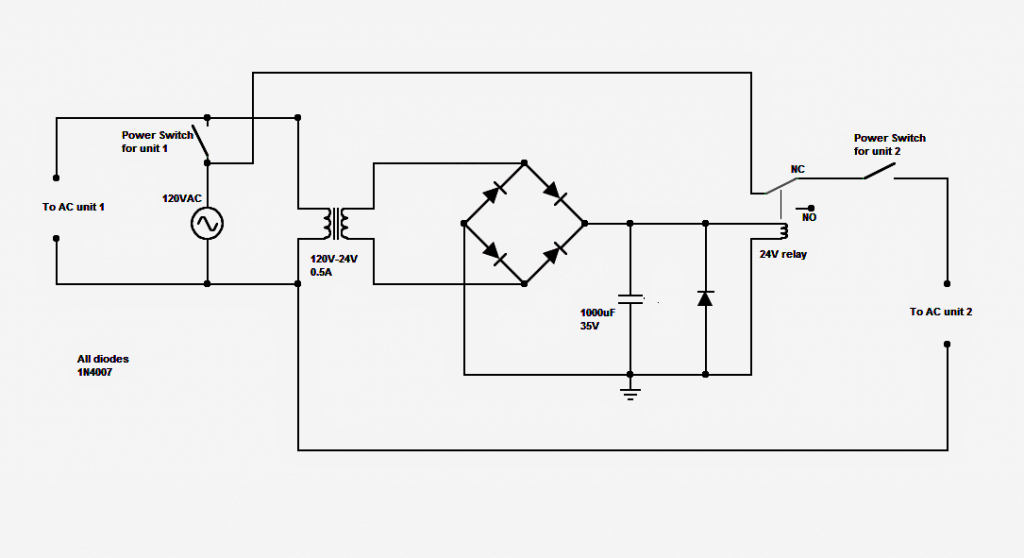
As can be seen, the design consists of a simple relay circuit which enables toggling of A/C1 and A/C2 in an alternate fashion, and never allows both to be activated at the same time.

In the circuit we have a transformer based full bridge rectifier power supply circuit with a "changeover" relay configured with its output potential. The power supply input is hooked up with the A/C power switch such that the relay activates whenever A/C 1 is switched ON.

The relay assembly has its contacts wired up with A/C 2 in such a way that as long as the relay is deactivated, A/C2 is allowed to get the switch-ON power through the relay's N/C contacts.

However the moment the relay toggles from its N/C contact to N/O, the power line for A/C2 is cut-off, fulfilling the intended purpose as discussed in the above sections.

You'll also like:

  • Grid Tie Inverter2C Wiring Details2C DiagramHow to Calculate Solar Panel, Inverter, Battery Parameters
  • Optimizing Grid, Solar Electricity with Inverter
  • IR2111 H-Bridge Inverter Circuit with Soft Start
  • the right way to interface SPWM with inverter MOSFETsDesign your own Sine Wave Inverter Circuit from the Scratch [Tutorial]

Filed Under: Inverter Circuits Tagged With: Changeover, Dual, Relay

About Swagatam

I am an electronics engineer and doing practical hands-on work from more than 15 years now. Building real circuits, testing them and also making PCB layouts by myself. I really love doing all these things like inventing something new, designing electronics and also helping other people like hobby guys who want to make their own cool circuits at home.

And that is the main reason why I started this website homemade-circuits.com, to share different types of circuit ideas..

If you are having any kind of doubt or question related to circuits then just write down your question in the comment box below, I am like always checking, so I guarantee I will reply you for sure!

Previous Post: « Input Trigger Synchronized Monostable Timer Using IC 555
Next Post: Simple Greenhouse Temperature Regulator Circuit »

Reader Interactions

Comments

EKEH EMMANUEL CHIJIOKE says:
April 17, 2015 at 6:43 pm

please i have a 3pole contactor of L1 to L3, please how can i use it as a changeover switch

Reply
Swagatam says:
April 18, 2015 at 4:28 am

If it's a relay, then you can use it as shown in the above link.

Reply
EKEH EMMANUEL CHIJIOKE says:
April 17, 2015 at 6:41 pm

i have an old ups which i detached the 12v 7ah batter and then inserted a 12v 100ah (2x) in parallel and also i built a charging unit for the battery outside the ups. now i want to ask instead me going to switch on and off d inverter when there is a power failure, can this ur changeover relay circuit be used to toggle between the mains and ups?

Reply
Swagatam says:
April 18, 2015 at 4:27 am

you can use the following circuit which looks more suitable for your need:

https://www.homemade-circuits.com/2012/09/automatic-inverter-supply-and-mains.html

Reply

Need Help? Please Leave a Comment! We value your input—Kindly keep it relevant to the above topic! Cancel reply

Your email address will not be published. Required fields are marked *

Primary Sidebar

circuit simulator image

Subscribe to get New Circuits in your Email

Categories

  • Arduino Projects (95)
  • Audio and Amplifier Projects (133)
  • Automation Projects (18)
  • Automobile Electronics (103)
  • Battery Charger Circuits (87)
  • Datasheets and Components (109)
  • Electronics Theory (149)
  • Energy from Magnets (27)
  • Games and Sports Projects (11)
  • Grid and 3-Phase (20)
  • Health related Projects (27)
  • Home Electrical Circuits (13)
  • Indicator Circuits (16)
  • Inverter Circuits (95)
  • Lamps and Lights (159)
  • Meters and Testers (71)
  • Mini Projects (28)
  • Motor Controller (68)
  • Oscillator Circuits (28)
  • Pets and Pests (15)
  • Power Supply Circuits (91)
  • Remote Control Circuits (50)
  • Renewable Energy (12)
  • Security and Alarm (64)
  • Sensors and Detectors (106)
  • SMPS and Converters (34)
  • Solar Controller Circuits (60)
  • Temperature Controllers (43)
  • Timer and Delay Relay (49)
  • Voltage Control and Protection (42)
  • Water Controller (37)
  • Wireless Circuits (31)

Other Links

  • Privacy Policy
  • Cookie Policy
  • Disclaimer
  • Copyright
  • Videos
  • Sitemap

People also Search

555 Circuits | 741 Circuits | LM324 Circuits | LM338 Circuits | 4017 Circuits | Ultrasonic Projects | SMPS Projects | Christmas Projects | MOSFETs | Radio Circuits | Laser Circuits | PIR Projects |

Social Profiles

  • Twitter
  • YouTube
  • Instagram
  • Pinterest
  • My Facebook-Page
  • Stack Exchange
  • Linkedin

Recent Comments

  • Swagatam on How to Make Dog Barking Preventer Circuit using High Frequency Deterrence
  • Swagatam on HX710B Air Pressure Sensor Datasheet, How to Connect
  • Yogesh on How to Make Dog Barking Preventer Circuit using High Frequency Deterrence
  • Klaas Hiemstra on HX710B Air Pressure Sensor Datasheet, How to Connect
  • Swagatam on HX710B Air Pressure Sensor Datasheet, How to Connect

© 2026 · Swagatam Innovations