In this post we are going to understand about how this DPDT relay actually works, how we identify its pinouts, and how we can use it in our projects. We shall go step by step so that you can feel confident with every small thing about it.
Introduction
We know that a DPDT relay means Double Pole Double Throw relay, so we can think that this relay has two separate internal switch sections and each section can connect with two different outputs.
That is why it is called Double Pole because it has two poles or two independent circuits and it is Double Throw because each pole can throw its connection to two different terminals, one Normally Closed and one Normally Open.

If you are not feeling interested to read the whole article below, you can simply watch the following video instead:
Basic Construction
We can see from outside that this DPDT relay looks like a small rectangular plastic box having six main terminals for switching and two extra pins for the coil.
The coil is the electromagnetic part that moves the inner switch and the remaining six pins are for two separate changeover contacts. So we can say that the relay has total eight pins, that is two pins for coil and six pins for contacts.
Pin Description
Let us now understand what each pin does in a very clear way. Inside the relay there are two sets of contacts.

Each set has three terminals, that is one Common or Pole pin, one Normally Closed (N/C) pin, and one Normally Open (N/O) pin. The coil pins are separate. So totally it looks like this:
Coil → Two pins that energize the relay
Pole 1 → Common contact for the first circuit
N/C 1 → Normally Closed terminal for first set
N/O 1 → Normally Open terminal for first set
Pole 2 → Common contact for the second set
N/C 2 → Normally Closed terminal for second set
N/O 2 → Normally Open terminal for second set
So as per many small blue or yellow DPDT relays, the order of pins normally comes like this: first two pins from one side are for the coil, the next pin after the coil is Common or Pole, the next middle pin is N/C, and the extreme last one is N/O. The same arrangement is repeated for the second set on the other side.
How The DPDT Relay Works
Now let us try to understand the working part. Inside the relay, when the coil is not energized, the common pole pin stays connected to the N/C pin.

So that time the N/O pin remains open, but since the relay is an electromagnetic type device, when we apply the rated voltage to the coil pins, then the coil becomes magnetized, and it pulls the inner moving contact from the N/C side to the N/O side.
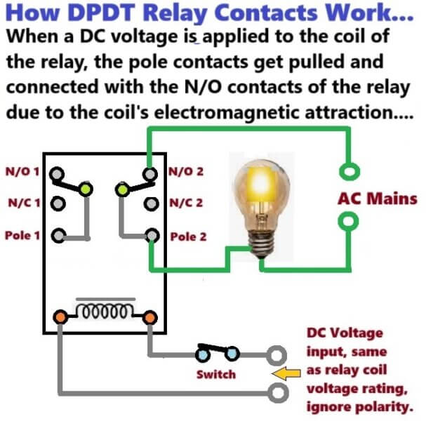
So we can say that before the coil gets power, the common stays with N/C. When the coil gets power, then the common moves away from N/C and connects with N/O.
And when the coil power is removed again, then the inner contact goes back to its resting N/C position due to the spring force. So it keeps toggling like that every time the coil is powered and de-powered.
Testing The DPDT Relay with Meter
Now we can learn a simple way how we can check the pinouts of this relay using a small multimeter. First we can set the multimeter to continuity mode or resistance mode.
Then we can find the two coil pins by checking between every pair of pins. The two pins that show low resistance (normally between 200 to 500 ohms depending on relay coil voltage) are the coil terminals.
After that we can keep the coil unpowered and check among the remaining six pins. We will find that in each group of three pins, one pin will show continuity with another pin, that means these two are Common and N/C.
The third one will show no connection, that is N/O. Now if we apply power to the coil then we will see that the continuity now shifts from N/C to N/O.
This simple test helps us to know the exact arrangement of pins and also confirms that the relay is working properly.
Practical Use Of DPDT Relay
Now we can discuss how we can use this relay in real circuits. Since it has two independent changeover sections, so we can control two different devices at the same time.
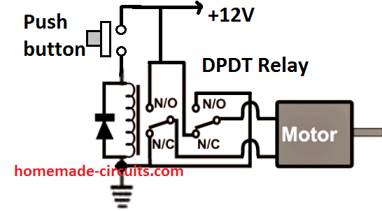
For example we can use one section to control positive line and another section to control negative line of a motor, so that we can reverse the rotation of the motor by changing the polarity through the relay.
We can also use it to change audio signals, switch power lines, or even switch between two different voltage sources.
Since the two poles are isolated internally, therefore we can use them for two unrelated circuits as well. So we can see that this DPDT relay is a very flexible and useful component for automation and control work.
Pin Orientation Confusion
But since there are many brands and types of DPDT relays, so the position of N/O and N/C pins can slightly differ from one brand to another.
Some relays have Common pin in the middle of each three-pin group and some have Common pin near the coil side.
So we should not depend only on online pictures or drawings, but instead we should always verify using multimeter before connecting it into any circuit.
Because then we can avoid wrong wiring and possible short circuits.
Summary
So now we have learned that the DPDT relay stands for Double Pole Double Throw relay which means it has two independent switching contacts. It contains eight pins in total, two for coil and six for switching external load with supply.
The coil creates a magnetic pull when we apply the rated voltage and that causes the internal armature to move and switch the contacts between N/C and N/O positions.
We can use this relay to control two separate loads, or we can use it to reverse a DC motor, or we can use it in any situation where two sets of changeover contacts are needed.



Comments (16)
https://docs.google.com/document/d/1Lxs2rC6iGu06ojTep2h6KOoZ0VeV3Dl3RRrvwcVBXQY/edit?usp=sharing
Hopefully that is reasonable, i tried to get Multisim ,however its makes my pc slow, but i will try it again today once more because i know that it kinda provide better schematics
Yes, you are right. First let the capacitors charge in parallel, then after they are full, switch the relay to series. Keep one voltmeter across each capacitor in both modes. Then add one more voltmeter across the two outer ends of the series capacitors, it should show the doubled voltage. Put the load across these same two outer ends after the relay switches to series.
Also, you do not yet have a proper load switching arrangement. If you connects the load permanently while the relay changes from parallel to series, the relay contacts may momentarily short or produce a high current surge.
so if I add a load the outer ends of the series capacitor, will it be fine right? and also can you please give a review regarding the circuit too please.
Yes, that right, but please change the relay setting and the load switchig in this way:
https://docs.google.com/document/d/1Lxs2rC6iGu06ojTep2h6KOoZ0VeV3Dl3RRrvwcVBXQY/edit?usp=sharing
Please do check that, comments are the link
Sorry, I cannot check a breadboard design, please show me schematic.
Or please tell me verbally what you see on the voltmeters when the relay is energized and when it is deenergized,
sorry…. well initially for example I thought me having a power supply that gives out 10 V , it would allow my capacitors to each store 10 V and with that being said I would have I would read 20 V initially when I measure voltage for capacitors connected in series so…that was my theory. simply because each stored 10V.
2. I wanted to control the load resistance with a potentiometer.
NB: the voltmeter readings for series and parallel I have attached them on the word doc if u could just scroll down please
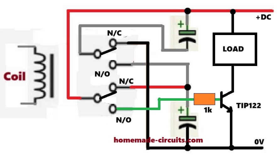
Yes, that is exactly what will happen with last circuit I gave you….the total will be 20V across the load. To adjust the load, just add a 1k in series with a 10k preset, at the collector of the BJT in my diagram.
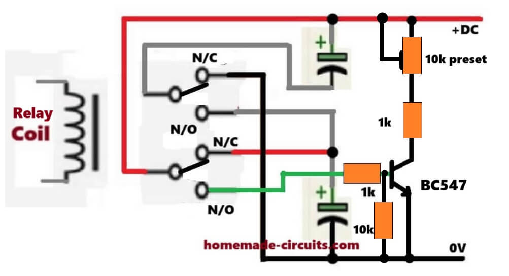
Hello, I have been having this idea that i want to try using a relay dpdt switch, so technically I want to use two capacitors which with energize and de-energize as they switch goes on and off. Basically, wonder if is it possible to have it to connect the capacitors in parallel and series? If yes, please help me out.
Hi, can you explain more elaborately, is the switch a power ON/OFF switch, how does the two capacitors need to energize and deenergize, do you mean when one capacitor is charged then other one is discharged and vice versa, alternately?
Hi, I am working on a solar charge controller project on Tinkercad and I need help understanding how to physically wire a DPDT relay together with two polarised capacitors to switch between series and parallel configurations.
Here is what I have:
– A DPDT relay with pins COM1, NO1, NC1, COM2, NO2, NC2
– Two polarised capacitors C1 and C2 acting as battery replacements
– A +20V power supply (will later be a solar cell)
– A common GND bus
What I need help with:
1. Where exactly does C1 negative and C2 negative connect on the relay
2. Which relay pins (NC or NO) create the parallel config and which create the series config
3. What voltage I should expect to see across the capacitors in each state
4. Why the voltage doubles in series but stays the same in parallel
The goal is for me to fully understand how the relay physically reroutes the current between the two capacitors before I wire it into my full solar charge controller circuit.
Can you walk me through the wiring step by step?
Hey, please check the following diagram, does it work for you?
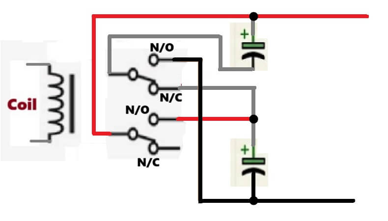
Well you gave me an idea, I need to work on my planning once more, however today i have been on the desk the entire day, try to figure out a way I can educate myself more about the functionality of this relay switch:
i tried to begin with a SPDT relay switch: https://www.tinkercad.com/things/7JQK1wm6Prb-neat-luulia/editel?returnTo=%2Fdashboard%2Fdesigns%2Fcircuits&sharecode=A1MRHmN8BcTlYI6GP-3GkBnCTA0e1YoXcQKHEZj3rtU
so, my circuit was inspired by the image u sent me and the circuit in the link attached below. This time I want to include a relay so that it can operate autonomously:
https://www.tinkercad.com/things/e1toVi86wwL-copy-of-relay/editel?returnTo=%2Fdashboard%2Fdesigns%2Fcircuits&sharecode=mSNg0-Ilr-VxN_4IZSH-IU8rZQdwoabxgQghNg5cgMI
However if u can have a look at the initial link that i have sent you, can you please tell me what could have i done better.
Sorry,, please send me a proper schematic diagram, checking a pictorial form can take lot of time…
Okay, I understand how the relay works.
my question is reversing a DC motor. So if I supply my power to NO 1 and NO 2 . Then run reverse leads from these to NC 1 and NC 2. Would this be acceptable?
So it would be NO 1 to NC 2 and NO 2 to NC 1, is that a proper way of set up?
Thank you
Thanks, yes you are correct, here’s a quick view of the connections: