• Skip to main content
  • Skip to primary sidebar

Homemade Circuit Projects

Need circuit help? Post them in the comments! I've answered over 50,000!

Blog | Categories | About | Contact | Calculators-online
You are here: Home / Arduino Projects / Digital Clock Circuit Using 16×2 LCD Display

Circuit Simulator: Assemble and Simulate

Digital Clock Circuit Using 16×2 LCD Display

Last Updated on December 5, 2024 by Swagatam 6 Comments

In this post I have explained how to make a simple digital clock using Arduino and a 16 x 2 LCD display.

Table of Contents
  • Introduction
  • Prototype Image:
  • Circuit diagram:
  • ARDUINO PROGRAM CODE:
  • Time setting:

Introduction

As an electronics enthusiast at a stage we would have thought, how to make a digital clock, especially who are interested in the field of digital electronics. In this article we are going to see how to make a digital clock and the design is so simple that a noob in Arduino can accomplish the project without any head ache.

This digital clock has just two main components, the Arduino and LCD display. The Arduino is the brain of the clock, which does mathematical and logical functions to updates the clock every second.

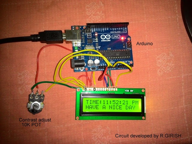
Prototype Image:

warning message: electricity is dangerous, proceed with caution
wire connection between the LCD and Arduino

The LCD screen is a standard 16 pin interfaced display. It has 16 rows and 2 columns, this means it can display 16 ASCII character in a row and it has two columns and that’s why it is called 16x2 display.

The wire connection between the LCD and Arduino is standard and we can find the similar kind of connections in most of the other Arduino-LCD based projects.

The potentiometer is used to adjust the contrast of the display.

The user must set this optimally so that the user can see the displayed digits/characters properly under all light situations.

There is backlight which enables the user to see the display during dark situation. The arduino can be powered externally from DC jack from 7 volt to 12 volt.

Circuit diagram:
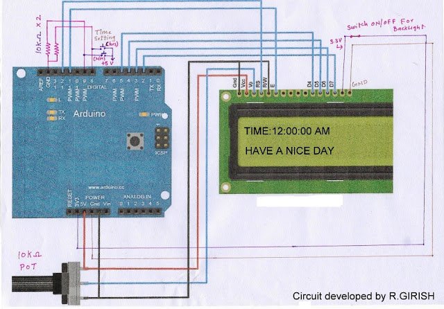
potentiometer is used to adjust the contrast of the display.

ARDUINO PROGRAM CODE:

//-------- Program developed by R.GIRISH-------//
#include <LiquidCrystal.h>
LiquidCrystal lcd(12,11,5,4,3,2);
int h=12;
int m;
int s;
int flag;
int TIME;
const int hs=8;
const int ms=9;
int state1;
int state2;
void setup()
{
lcd.begin(16,2);
}
void loop()
{
lcd.setCursor(0,0);
s=s+1;
lcd.print("TIME:" );
lcd.print(h);
lcd.print(":");
lcd.print(m);
lcd.print(":");
lcd.print(s);
if(flag<12) lcd.print(" AM");
if(flag==12) lcd.print(" PM");
if(flag>12) lcd.print(" PM");
if(flag==24) flag=0;
delay(1000);
lcd.clear();
if(s==60) {
s=0;
m=m+1;
}
if(m==60)
{
m=0;
h=h+1;
flag=flag+1;
}
if(h==13)
{
h=1;
}
lcd.setCursor(0,1);
lcd.print("HAVE A NICE DAY");
//-----------Time setting----------//
state1=digitalRead(hs);
if(state1==1)
{
h=h+1;
flag=flag+1;
if(flag<12) lcd.print(" AM");
if(flag==12) lcd.print(" PM");
if(flag>12) lcd.print(" PM");
if(flag==24) flag=0;
if(h==13) h=1;
}
state2=digitalRead(ms);
if(state2==1) {
s=0;
m=m+1;
}
}
//-------- Program developed by R.GIRISH-------//

NOTE: The above program is verified and error free. In case you got any warning or error, please add the LiquidCrystal library manually.

Time setting:

There are two push button one for setting hours and another for setting for minutes. Pressing either one will increment the corresponding digits. For setting hours press hrs the button till the correct time displays, similarly for minutes.

NOTE:

· While setting time the keep the button depressed till the desired time reaches. Pressing the button momentarily may not change the time.

· Each digit gets incremented only second after second, this is because the whole loop of the program delayed for 1 second.

· The seconds’ digit goes from 01 to 60 and loops again and won’t display “00” as traditional digital clock does.

You'll also like:

  • 1.  Arduino LCD KeyPad Shield (SKU: DFR0009) Datasheet
  • 2.  Incubator Using Arduino with Automatic Temperature and Humidity control
  • 3.  Transformerless AC Voltmeter Circuit Using Arduino
  • 4.  Arduino IR Remote Control Circuit
  • 5.  Wireless Servo Motor Control Using 2.4 GHz communication link
  • 6.  50 Best Arduino Projects for Final Year Engineering Students

Filed Under: Arduino Projects Tagged With: 16x2, Clock, Digital, Display, LCD

About Swagatam

I am an electronics engineer and doing practical hands-on work from more than 15 years now. Building real circuits, testing them and also making PCB layouts by myself. I really love doing all these things like inventing something new, designing electronics and also helping other people like hobby guys who want to make their own cool circuits at home.

And that is the main reason why I started this website homemade-circuits.com, to share different types of circuit ideas..

If you are having any kind of doubt or question related to circuits then just write down your question in the comment box below, I am like always checking, so I guarantee I will reply you for sure!

Previous Post: « Solar Inverter for 1.5 Ton Air Conditioner
Next Post: Simple Vertical Axis Wind Turbine Generator Circuit »

Reader Interactions

Comments

  1. Sayantan says

    April 25, 2018 at 11:22 am

    I want to add alarm features to this project .What will be the complete program code for that ?

    Reply
    • Swagatam says

      April 25, 2018 at 2:10 pm

      designing customized codes will require a fee to be paid for the service

      Reply
  2. Basanta Panigrahy says

    December 19, 2016 at 10:57 am

    Sir can you send sketch for multi function ledchaser 12 channel

    Reply
  3. Kaushik Mb says

    June 6, 2016 at 6:29 pm

    dude the time lags for about 10mins a day, so for a week its about an hour slow…

    Reply
    • GR says

      June 11, 2016 at 1:43 am

      Hi kaushik,

      The time lag is due to the ceramic based resonator in the ATmega328P, the delay function is independent of the crystal. It varies with ambient temperature, but we can compensate it by adding few millisecond to delay function, for example try delay(1050); instead of delay(1000); calculate the time lag and add few milliseconds.

      If your clock leads the time try reducing delay.

      Regards

      Reply
    • Kaushik Mb says

      June 11, 2016 at 4:40 am

      Thanks for the reply GR, due to the time lag problem, i purchased an RTC DS1307 IC, i still dint try with it. Hope it works well…

      Reply

Need Help? Please Leave a Comment! We value your input—Kindly keep it relevant to the above topic! Cancel reply

Your email address will not be published. Required fields are marked *

Primary Sidebar


Subscribe to New Posts

Categories

  • Arduino Projects (89)
  • Audio and Amplifier Projects (132)
  • Automation Projects (17)
  • Automobile Electronics (101)
  • Battery Charger Circuits (83)
  • Datasheets and Components (104)
  • Electronics Theory (143)
  • Free Energy (37)
  • Games and Sports Projects (11)
  • Grid and 3-Phase (19)
  • Health related Projects (25)
  • Home Electrical Circuits (12)
  • Indicator Circuits (14)
  • Inverter Circuits (88)
  • Lamps and Lights (142)
  • Meters and Testers (69)
  • Mini Projects (46)
  • Motor Controller (64)
  • Oscillator Circuits (27)
  • Pets and Pests (15)
  • Power Supply Circuits (108)
  • Remote Control Circuits (50)
  • Security and Alarm (64)
  • Sensors and Detectors (101)
  • Solar Controller Circuits (59)
  • Temperature Controllers (42)
  • Timer and Delay Relay (49)
  • Transmitter Circuits (29)
  • Voltage Control and Protection (39)
  • Water Controller (36)


Other Links

  • Privacy Policy
  • Cookie Policy
  • Disclaimer
  • Copyright
  • Videos
  • Sitemap


People also Search

555 Circuits | 741 Circuits | LM324 Circuits | LM338 Circuits | 4017 Circuits | Ultrasonic Projects | SMPS Projects | Christmas Projects | MOSFETs | Radio Circuits | Laser Circuits | PIR Projects |

Social Profiles

  • Twitter
  • YouTube
  • Instagram
  • Pinterest
  • My Facebook-Page
  • Quora
  • Stack Exchange
  • Linkedin


  • Recent Comments

    • Swagatam on How to Repair Mosquito Swatter Bats
    • Pradosh on How to Repair Mosquito Swatter Bats
    • Swagatam on 100A AC Load Monitoring Circuit using Arduino, Watt Limit, LCD, Alarm, Auto Shutdown
    • Swagatam on How to Modify 78XX, LM323, LM350, LM317 Voltage Regulator Circuits
    • Swagatam on 5 Simple Audio Mixer Circuits Explained

    © 2025 · Swagatam Innovations